Pro Tuning Guide
The printer should be turned off, and ideally unplugged, before attempting any tuning. Attempted movement of the printer axis while powered could result in damage to yourself or to the printer. Ensure that the hot end has cooled off completely before attempting any tuning as well.
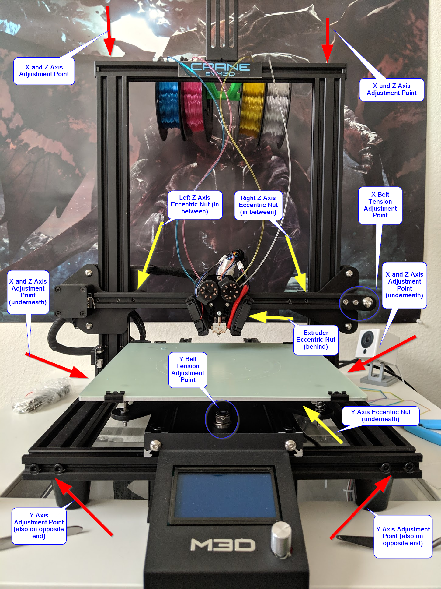
The M3D Crane printer has a number of adjustment points for each axis. In the picture below, the red arrows indicate adjustment points for the frame, the yellow arrows indicate eccentric nuts for adjusting the tension on each axis, and the blue circles indicate the tensioning point for the belts.

Each type of adjustment requires a different set of tools, so review the list below before getting started.
Tools Required
For frame adjustments:
5mm hex key (allen wrench)
For eccentric nut adjustments:
10mm open end box wrench
8mm open end box wrench
4mm hex key
For belt tensioning adjustments:
6mm hex key (allen wrench)
12mm socket wrench
How to Adjust
Before we begin, it is important to understand how each of these adjustment points function.
The following frame adjustments were already performed at the factory and are not necessary for most users. You should only need to adjust the frame if you have previously taken the printer apart, or ave adjusted all eccentric nuts and are still experiencing binding at certain points on your axis.
Frame Adjustment
To adjust the frame adjustment points, you simply loosen the hex nut bolts in the frame (2 at each point) with a 5mm hex key and twist the metal frame extrusions slightly. There won't be much movement for most of the adjustment points, and it may feel like it's not moving at all, but it is important to ensure these contact points are equal and square, otherwise your axis may bind or you may have erratic print behavior at the extreme ends of your print volume.
Eccentric Nut Adjustment
Moving on to the eccentric nuts - This will be the most common type of tuning you perform on your printer. To begin adjustment of an eccentric nut, you take the 4mm hex key and place it in the hex head of the bolt running through the wheel and the eccentric nut. On the other end, you will place the 8mm open end box wrench and loosen the bolt slightly. It does not need to be very loose, and if it is too loose, that will impact your ability to adjust the eccentric nut effectively. Once the bolt is loosened slightly, you can then take the 10mm open end box wrench and spin he larger nut in between the wheel and the build plate. The nut is offset slightly so that as it spins it applies a different amount of pressure between the wheel and the plate. I recommend spinning the nut around completely at least once to get a feel for how the tension changes as it rotates around the bolt. Don't worry about "over tightening" the eccentric nut, as it doesn't actually tighten at all. It spins freely around the bolt with no threads running through the center. You can adjust the eccentric nut in either direction, so play around with it to get a feel for how it adjusts.
Once you've found the desired tension on the eccentric nut, you will need to tighten the bolt back down using the 4mm hex key and the 8mm open end box wrench using the same process you used to loosen it. You're not trying to tighten the bolt down completely, you're just trying to make it snug enough so that the eccentric nut cannot be moved easily and is held in place. It's important to note that when tightening the bolt, it will slightly tighten up the eccentric nut a little more than what you adjusted it to, so it may take a couple tries before you get the feeling down of how tight each eccentric nut and wheel should be.
X Axis
Print Head Eccentric Nut

When properly tuned, the print head should move easily side to side, but should not wobble front to back, nor should the x chassis wobble front to back on the chassis (See Z Axis tuning for adjustments of the X Chassis).
Process
Begin by loosening the bolt holding the print head's eccentric nut.
Next, adjust the tightness of the eccentric nut by rotating it until the print head is held firmly in plac.
All 3 wheels should be in contact with the rail when properly adjusted.
When holding the print head steady, you should not be able to rotate any of the wheels on the print head chassis without also moving the print head.
Move the print head back and forth and attempt rocking it slightly
The print head should move left to right easily and the chassis should not rock front to back.
There may be a small amount of play in the connection of the print head to the bracket.
If this feels like it's too loose, you can remove the print head by loosening the eccentric nut's bolt until the wheel is loose enough to pop the print head chassis off. There are two screws on the back side of the chassis that you can use to tighten the print head to the print head chassis.
Tuning Results
Y Axis
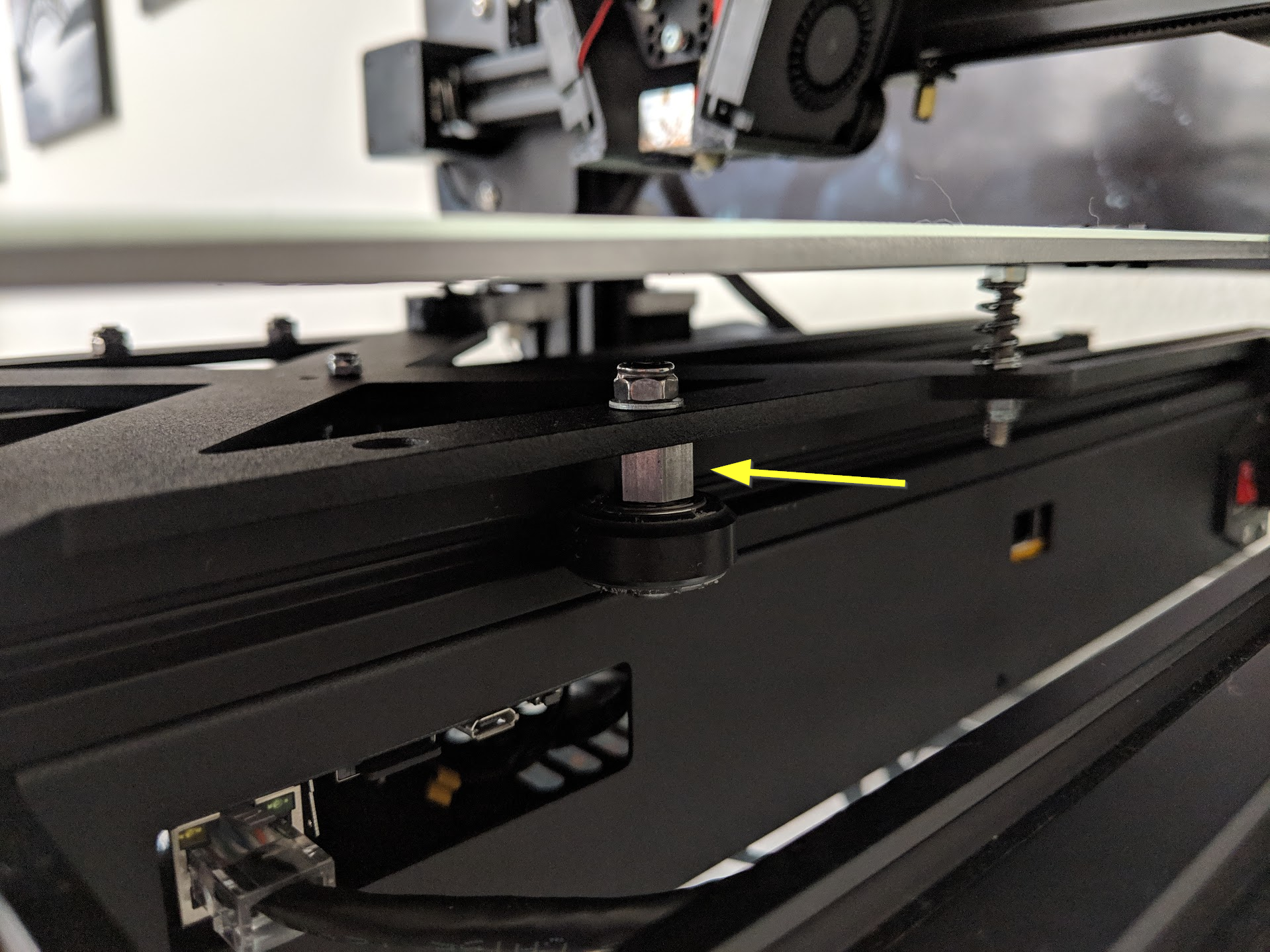
Build Plate Eccentric Nut

When properly tuned, the build plate should move front to back easily and smoothly, but should not rock or tilt. Having a tight and properly aligned build plate is important for ensuring a level, consistent bed. In addition to the eccentric nut on the build plate, the Y axis can also be adjusted by 4 frame mounting points, but this has been adjusted at the factory and is not necessary for most users. Only the eccentric nut adjustments are covered below.
Process
Slightly loosen the bolt holding the build plate eccentric nut, under the right hand side of the build plate.
Adjust the eccentric nut for the Y axis until it the platform feels snug and sturdy, and the wheel cannot move without also moving the build plate.
Ensure the plate can move easily all the way along the Y axis.
If there are any tight spots, you may need to loosen the frame bolts related to the Y axis and re-tighten them evenly.
Once the Y axis is moving freely, tighten down the bolt holding the eccentric nut and test the movement once more.
Tuning Results
Z Axis
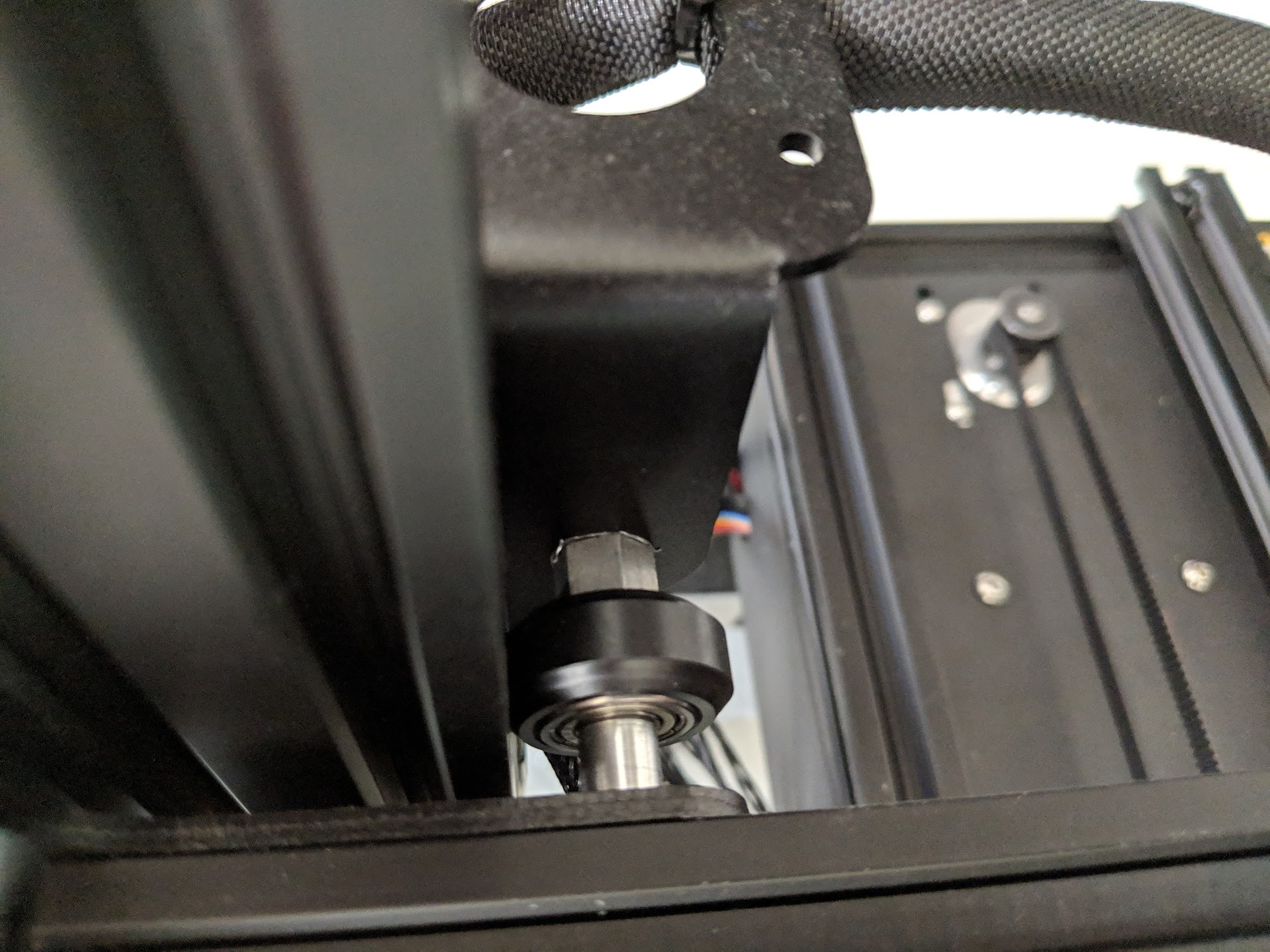
Z Chassis Left Eccentric Nut

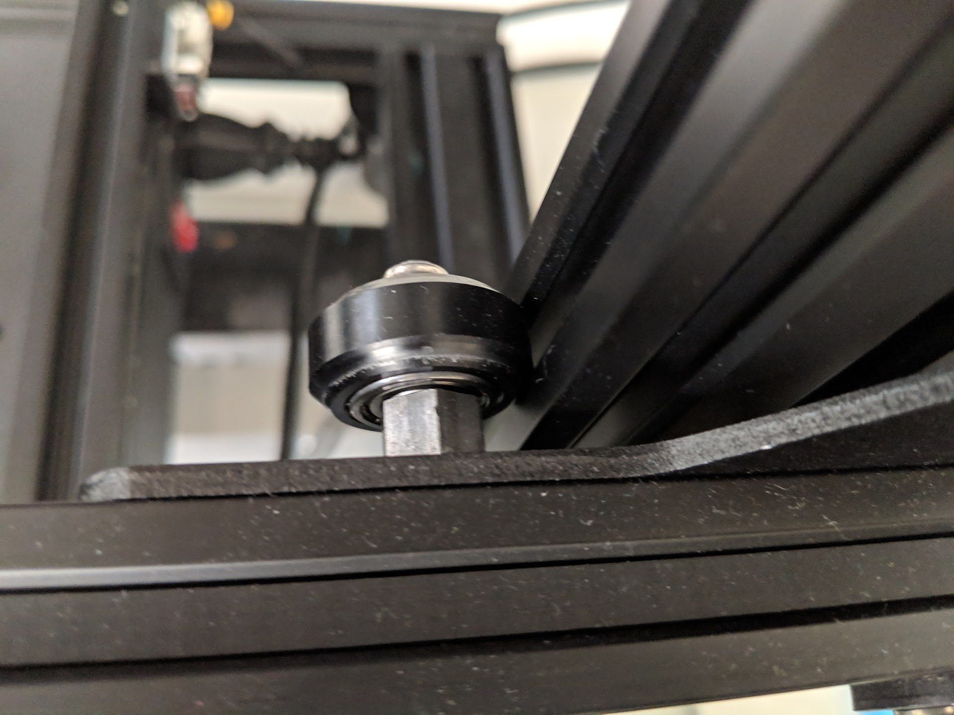
Z Chassis Right Eccentric Nut

When properly tuned, the Z axis (X Chassis) should be able to move up and down with one hand and should not rock back and forth any. It should be evenly spaced to the top frame on the left and right side as well. Machine oil, or similar lubricants, can be used on the lead screw to aide in ease of movement. Lubrication of the lead screw plays a substantial part in the ease of movement of the Z axis and should generally be one of the first places you check if you are experiencing binding or rough spots in your Z movement. Under manual force, the movement should be consistent and smooth from top to bottom of the Z axis range.
There are 2 primary points of adjustment (eccentric nuts) and 4 secondary points of adjustment (frame attachment points). Only the eccentric nut adjustments are covered below.
Process
Move the X Chassis all the way to the top or bottom of the axis (I recommend bottom).
Start by loosening the right side eccentric nut to the point that the wheel is still touching the frame, but can spin freely by hand without moving the chassis.
Afterwards, loosen the left side eccentric nut to the same point.
Test the movement of the X Chassis up and down.
It may be slightly difficult to move at this point due to some minor torquing of the chassis on the lead screw.
Adjust the left side eccentric nut so that it tightens up agains the railing a small amount.
At this point, the left eccentric nut wheel should be snug against the frame and the right side should still be slightly loose.
Go ahead and tighten up the right side eccentric nut until all three wheels are touching the frame and the wheel can no longer spin freely.
Each side (left and right) should feel tight, but not to the point of inhibiting movement.
Now, you can test moving the X Chassis up and down and feel how it moves.
There should be no wobble in the front to back direction, and the X Chassis should be capable of moving up and down with minor effort.
You can apply a small amount of machine oil to the 4 channels of the lead screw to aide in movement of the X Chassis. Move the chassis up and down slowly to help spread the oil along the lead screw
Tighten back down the bolts on the left and right side eccentric nut bolts and test movement again.
If the axis movement is too stiff after tightening the bolts, ensure you have not over-tightened them, then follow the above steps to loosen the eccentric nuts slightly in order to provide a little more movement freedom, re-tighten the bolts again, and check once more.
Tuning Results
Last updated