# Welcome
Information on your M3D Crane Series printer.
Welcome and thank you for choosing the M3D Crane series of printers! This is the getting started / quick-start guide for the Crane Series 3D Printer. First select the Model style of M3D Crane you have purchased and you will be directed to the Quick Start Guide that matches your new printer.
NEW - July 2019 WalkThrough / Crash Course: For users setting up their quad head for the first time and looking to gain a deep understanding of the system to get the best results, start [here](https://coda.io/d/M3D-Official-Troubleshooting-Self-Help-Guide_dzE73kMbIAL/Quad-Expert-Crash-Course_sudLH#_luBEE).
For troubleshooting please visit the [Self-help guide](https://coda.io/d/M3D-Public-Coda-Self-Help-Support_dzE73kMbIAL/Crane-Troubleshooting_suMmY#_lu4jO)
| \*\*\*\*[**The Crane Bowden**](https://crane.printm3d.com/crane-bowden-guide/crane-bowden-unboxing-assembly)\*\*\*\* | [**The Crane Dual**](https://crane.printm3d.com/crane-dual/unboxing-and-assembly)\*\*\*\* | \*\*\*\*[**The Crane Quad**](https://crane.printm3d.com/crane-quad-guide/unboxing-and-assembly)\*\*\*\* |
| :------------------------------------------------------------------------------------------------------------------: | :---------------------------------------------------------------------------------------: | :-----------------------------------------------------------------------------------------------------: |
|  |  |  |
| ------------------------------------ | ------------------------------------ | ------------------------------------ |
# Warnings
Please read through all the warnings as they may save you from making a mistake that could result in injury to yourself or your M3D Crane Series printer.
## Warnings
1. DO NOT TOUCH PRINTER WHILE OPERATING The Crane is a powerful machine. While the Crane is moving or printing you should not reach into the buildspace.
2. AVOID MOVING WITHOUT POWER
3. MOVE MOTORS/BED/EXTRUDER SLOWLY
Moving motors generates power on all printers and can damage your board. There is no clear indicator of the power you are generating however when moving very fast the fans may start to turn. If you can hear the fan moving air, you're close to voltages that will break the duet regulator (more than 28V). Moving components about 50mm/s is safe. It is best to always move components while the system is powered.
4. DISABLING MOTORS
When you disable motors the printhead may drop extremely slowly to the limit switch. This is normal behavior and requires rehoming.
5. ESD SAFETY:
The Duet contains an ARM class 2 processor, we recommend you use a wrist straps when touching any wires that could send shocks to the main processor and fry it.
6. DON'T USE AN ESD WRIST STRAPS TIED TO A SURGE STRIP
The printer is grounded. If you wire the strap wrong it can cause a short circuit through your body whenever you touch the printer.
7. USE UNDER SUPERVISION
Use product in locations where nothing can catch on fire should the worst occur. The Crane is constructed out of metal and fireproof materials. Still, PLA and other filaments can burn fire if the printer is used improperly.
8. MAXIMUM EXTRUDER SPEED
It is a common misconception that printhead travel movement speed (i.e. 60 mm/s) is the limiting factor when printing. However, it is extruder volumetric (or mass) flow rate that is the true limiting speed in most conditions. It is not easy to be able to exceed 9 mm^3/s (PLA) and 12 mm^3/s (Higher temp materials like PETG, ABS) except in special cases. To calculate flow rate multiple head speed, layer width, and layer height. For example: 45mm/s movement, 0.3 mm layers and 0.5 mm wide would be 6.75mm^3/s.
9. Z SPEED
The bed current, acceleration and speed are configured for worse case scenarios like heavy prints. You can increase speeds when printing lighter items or depending on your application of the printer.
10. BED TEMPERATURE
If you are using a glass print bed, give the printer an extra few minutes to reach temperature. In open air, the glass surface will be 5-10 C cooler than the bed temperature readouts from the thermistor.
11. FRAME CAN BE SHARP
The frame of the printer is metal and could contain sharp edges. Use caution when moving the printer or moving around the printer. Keep your hands out of the machine during operation and be careful when lifting.
12. BURN HAZARD
BED and NOZZLES are hot!
13. USE CAUTION WHEN REMOVING PRINTS
The best strategy is to let the bed cool, most prints pop off by themselves.
14. REMOVING DUET SD CARD DISABLES FEATURES
The Duet relies on its microSD card to serve as memory, storage for the LCD menu structure, duet webhost, and basic configurations. Without this card you can not connect over ethernet or use the LCD, however USB will still work. We do not recommend removing it. There is an SD card slot under the LCD providing a card slot physically moving print Gcode files, or use the web interface to upload Gcodes.
15. It should be noted that each Crane Series printer has a Voltage switch on the right hand side of the machine. For operation in the US the voltage must be set to 115.
# Facebook Group
**M3D QuadFusion and Dual Owners Group**
an Unofficial Community Run Group, Officially supported by M3D.
Are you a M3D Quad or Dual Owner? Do you have interest in being one?
Then check out the Lively Group of M3D Quad/Dual Owners who are all active and available to interact with. Technical Help, Moral Support and Team Work Drives this community, where their moto is "Help One Another, Encourage and Create Awesome!"
* General Product *FAQs*
* Troubleshooting
* Printable Files, SD Card images, Sample Slicer Settings and more...
Please visit the [M3D QuadFusion and Dual Owners Group](https://www.facebook.com/groups/287867492126710) for more information.
# Coda For Troubleshooting
Please visit the [M3D Troubleshooting CODA](https://coda.io/d/M3D-Official-Troubleshooting-Self-Help-Guide_dzE73kMbIAL/Crane-Troubleshooting_suMmY#_lu4jO) for more information such as:
* General Product *FAQs*
* Troubleshooting - Procedures for proper identification of problems, diagnostic tests the user can try at home in order of the most likely issues first, and procedures to solve selected confirmed problems
* Product Specifications
* Printable Files, SD Card images, Sample Slicer Settings and more...
# Unboxing/Assembly
{% hint style="warning" %}
The M3D Crane Bowden contains sensitive electronics, delicate mechanical parts, and an electrical heating system. Please exercise all applicable safety precautions and follow this guide closely to avoid damage to your M3D Crane Bowden, to avoid injury to yourself or others, and insure proper operation. Check your Local Supply Voltage and set your printers Voltage accordingly, or risk damage to your printer.
{% endhint %}
## Setting up after unboxing your printer:
After removing your M3D Crane Bowden from the box, remove all the plastic wrapping being careful not to cut any of the sensitive parts of the device, such as the cables. Your M3D Crane Bowden should look like this:

Remove the bolts at the bottom of each upright rail, as shown below. Setting them aside briefly:


{% hint style="warning" %}
Inspect your M3D Crane Bowden for any damage that may have occurred during shipping. Every precaution has been made to prevent this, however it is advisable to give all the components a thorough inspection before operation. If any issues are discovered, document the damage by taking an image of the affected area and contact M3D immediately.
{% endhint %}
As long as no issues are discovered, you are ready for mechanical assembly.
## Assembly:
Being careful not to stress or pull any of the cables, have a friend assist you in raising the upright rails; be sure to **align the bolt holes**.
If you aren't able to hold the upright in place, get someone's help to steady it. Line up the bolt holes(that previously housed the bolts you removed) and begin slowly tightening the bolts; first hand tighten, then slowly tighten more firmly with the provided **Allen Key**.

Ensure that all motor cables are connected. These are part of the **black ribbon cable**. You can identify the correct motor cable by looking at the **yellow tags reading 'X, Y, and Z'.** The motor connections are made up of 4 wires, while the associated endstop cable is a three wire cable directly beside the 4-wire cable for the respective motor; the only motor without an endstop is the extruder.


Connect the two gray ribbon cables labeled '1' and '2' and connect them to their respective ports on the back of the LCD assembly, 'EXP1' and 'EXP2'. **Be careful not to cross these connections as it may damage the LCD Screen.**


Should you find that your LCD cables are not labeled, simply determine which cable is **shortest**, that will be the cable to be connected to **EXP1**.


Connect the **short cable to EXP1**, plug the **longer** **cable into EXP2**, and proceed to the next step.

After making the connections, use the provided bolts and Allen Key to secure the LCD to the front of the M3D Crane Bowden.

## Z-endstop positioning:
Be sure your M3D Crane is powered off and/or unplugged before you begin this step.
In order to ensure nothing is damaged during shipping, and furthermore during the first power on of your M3D Crane, it's been shipped with the Z-endstop raised. You will need to manually lower your Z-endstop before printing.

The first step to moving your Z-endstop to an appropriate height is to examine the exposed bolts below the Y-carriage and to tighten/loosen all four of your bed nuts so that only about 8-10 threads are exposed on each. You can see in this photograph a bolt that has been tightened to its recommended position. Use your own 7mm or 1/4th inch wrench to ensure each bolt is adjusted to approximately the same position.

Next you will need to manually center the print head over the bed. To do this gently move the print head left-to-right along the X-axis until it's in the center. Then, move the bed forward along the Y-axis until its center. At this point, the print head should be above the center of the bed. Finally, rotate the coupler between the Z-motor and the Z-leadscrew counter-clockwise until the left bracket of the X-axis is resting on top of the Z-endstop switch as seen in the photo.


The Z endstop is attached to the rail with two T-nuts that hang the inside of the aluminum extrusion channel. Loosen the Z endstop bracket enough to loosen the 2 screws that secure the bracket to the rail.
After loosening the Z-endstop and allowing it to move down, we are now free to move the printhead closer to the bed. Slowly lower the print head until the nozzle touches the bed.
Little by little raise the Z endstop until a click is heard/felt and then tighten down the 2 screws again. You should be able to secure one of the nuts fairly easily to maintain the position of the Z endstop.
Manually raise your print head by rotating the Z axis and now you are ready to power on the M3D Crane and select Home All in the LCD menu. While it is still necessary that we run through the leveling process with the printer powered on, making these changes ensures that we do not cause any damage to the print surface.
In order to assure your M3D Crane Series printer maintains an accurate bed level after following the [Bed Leveling](https://crane.printm3d.com/~/edit/drafts/-LTi556ASBKSVfOwPujM/crane-bowden-guide/manual-bed-leveling) section of this guide it may be necessary to make further adjustments to the Z endstop position. Maneuvering the Z endstop in conjunction with following the Bed Leveling guide will lead to a more accurate and level print bed.
## X Bracket Alignment and tightening:
Should you notice your x bracket, the plate attaching the print head to the x axis is loose OR too tight follow the instructions in the pro-tuning guide to learn how to loosen or tighten the eccentric nuts that secure the x bracket to it's axis.
Should your x bracket appear warped or bent, please be sure to check that the eccentric nuts are not too tight. It should be secure enough so that then print head doesn't move around during printing about 1/16-1/12th turn extra past this point on the eccentric nuts should be sufficient any tighter could result in the appearance of warping or bending of the x bracket. Loosing these eccentric nuts should remedy this.
## Rubber Feet:
If your Crane is shipped without the feet assembled, please follow this videio instruction guide
{% embed url="" %}
## Spool Holder:
The M3D Crane Series comes equipped with a heavy duty spool holder. This Spool Holder well suited to hold the larger spools of 500 or 1000 feet of Filament. Here we show how to assemble the Spool Holder:

The Spool Holder is comprised of the following parts:
* 2 T-nuts
* Mounting Bracket
* Spool Mount Spindle
* 2 End Caps

To assemble the Spool Holder screw the T-nuts into the holes at the bottom of the Mounting Bracket. Be sure to leave them fairly loose as you will tighten them firmly once the Mounting Bracket has been attached to the top rail of your M3D Crane Bowden printer.

Once the T-nuts are in place, slip one end of the Spool Mount Spindle through the large hole in the top of the Mounting Bracket and secure with an End Cap.

The Spool Holder is designed so that the End Cap secures the spool and prevents it from slipping off the Spool Mount Spindle while in use. When not in use it's advised to keep the End Cap secured to the Spool Mount Spindle to prevent it from becoming lost or misplaced.

Once your Spool Holder is fully assembled simply slip the T-nuts into the grove on the top rail of your M3D Crane Bowden printer and tighten securely.
{% hint style="danger" %}
Prior to exiting this section, please double check all connections, and place your crane on a flat surface. Ensure the Power Switch is Off(O), double check that your voltage is set appropriately for YOUR area(consult local authorities if you are unsure). **Failure to do this can irreparably harm the electronics in your printer.**
{% endhint %}
## Finished M3D Crane Bowden:
Once your M3D Crane Bowden is complete it should look like this:

## Endstop Damage:
{% hint style="info" %}
Occasionally things can be damaged during shipping, and or come loose. If you notice that one of your end-stops has broken, you can swap any of the others to replace the Z end-stop as this one is the most important.
{% endhint %}

## Printsheets, Glass Bed and/or Adhesive Print Surface:
Depending on when you received you Crane, and which add-ons you included, your printer may come with one of three options. Here they are and when they should be used:
* Black adhesive sheet - This is best used as a texture enhancer, since when properly calibrated, the bottom of prints will not look 3D printed, but matte finish. It is a bit more forgiving of height variations and thus better for first time prints, and prints with very small features on the first layer, like thin legs. This material tends to rip with repeated use, especially with higher temperature materials and is thus a consumable. It's best practice to put this on a replacable material like the fiberglass sheet, otherwise adhesive removal may leave residue on the heated bed.
* Unbound / Light Yellow-Green Fiberglass sheet with clips - This is the recommended surface, as it does not need any glue applied on the surface to work, and the nozzle can not easily melt and damage it. We recommend this for repeated printing, and especially for printing higher temperature materials like PETG (M3D's ABS-R). To bind PETG prints, heat to 80-85C, and to remove them cool below 60C. Prints should pop off easily when cold, so it isn't the best option for power-fail recovery.
* Thick Glass Bed with clips - This is a more traditional print surface. It's best use case is when making extremely shiny and flat prints. However, it has adhesion issues and is not good for small features or large dense prints. Glue or adhesive spray needs to be applied to get a good bond, and this aspect of using a glass bed is artistic in that everyone has a different approach. We recommend starting with elmers glue stick, and applying two very thin layers when hot.
## Before powering on your M3D Crane Series Printer:
You should have received along with your printer, a micro SD card as well as a blue micro SD card adapter. Check the SD card slot on the right side of your Crane Series printer to see if yours was shipped with the SD card already in place. If your SD card is already in place, remove it and replace it before powering it on. The SD card may have been shifted or impacted during shipping and turning on the power with the SD card askew inside could lead to damage.
If your SD card has arrived in a small separate case, simply remove the SD card from it's package and place it into the SD card slot on the right side of your Crane Series printer.
The Crane Series of printers are unique in that they are built with a Duet Maestro board. The Duet board uses the information on the SD card to operate, in a sense the SD card that goes in the slot on the Duet acts like it's hard drive. It is for this reason that should you desire to use an SD card to move your gcode to your printer instead of using Duet Web Control, it's recommended to purchase a second micro SD card and use the SD card slot on the back of the LCD screen.
## Additional information:
After assembly you may have some questions that might be further discussed in our[ Pro Tuning Guide](https://crane.printm3d.com/advanced-tuning-m3d-crane-series/tuning-guide).
Congratulations!! You have completed the Assembly of your M3D Crane Bowden Printer!! In the next section you will learn how to include your new M3D Crane Bowden into your existing network, or set up a network from scratch.
# First time Network Setup
Connecting to your M3D Crane Series Printer via your local network is very useful as you get access to the **Duet Web Console**. You can connect your M3D Crane Series Printer to your local network via the **Ethernet port on the Duet Maestro.** Once the network settings are properly configured, you will be able to connect to the **Duet board** and access the **Duet Web Console**.
## First-Time Start-up
{% hint style="info" %}
The M3D Crane Series printers are pre-configured to easily work with the most common network configuration, **DHCP**. If however you have a more complex network configuration, it may be necessary to further edit your network settings.
{% endhint %}
Pre-configured network settings are loaded onto every SD card before the printer goes out our door, these network settings utilize **DHCP** in order to get an IP address from your router. This should allow your M3D Crane Bowden to connect automatically to your network.
Once connected via **Ethernet** your M3D Crane Series printer will display an **IP address** on it's LCD screen.

Once connected via **Ethernet** your M3D Crane Series printer will display an **IP address** on the Main Menu of the LCD screen. After your printer has had the time to start up, direct your browser to the address http\://\. If the connection is successful the **Duet Web Control** should be shown. You have completed the network setup. If you are unable to access Duet Web Control you may need to contact your Network Administrator.

In the next section you will learn how to navigate through the LCD menu of your M3D Crane Bowden Printer.
# LCD Menu Navigation
## Getting to know your M3D Crane Series printer's LCD Menu Display:
Below is an image of the **Standby screen** of your M3D Crane Series printer. While in **Standby** mode, or while it's not actively printing the LCD screen will display the following information:

* **Nozzle**: this will display the nozzle's **current temperature as well as the nozzle's set temperature**. To **Set the Nozzle Temp** simply move the knob in order to **highlight the temperature values** in the Nozzle row. Once highlighted, **depress the knob once to select**, then **turn the knob until the desired temperature is displayed** and select by depressing the knob once more.
* **Bed**: this will display the c**urrent bed temperature** as well as the **set bed temperature**. To set the Bed Temp, simply follow the directions as if you were changing the nozzle temp but apply them to the Bed row.
* **Feed Rate**: this displays your **current feed rate**. To change the **Feed Rate**, simply **select the value and adjust with the knob.**
* **IP**: this displays the **IP address of your M3D Crane Series printer on your network**. The **Network Setup** section of this guide shows how to access the **Duet Web Control Interface** via this IP address. The displayed values of the IP address are not able to be selected nor changed from this menu.
* **Prepare**: selecting Prepare will change the LCD screen Menu to an additional menu page.
## Prepare: Or Main Menu page 2
* **Back to Main**: selecting Back to Main will bring you back to the Main, or Standby menu.
* **Move Axis**: selecting Move Axis will bring you to a sub-menu where you can select each axis including the extruder, in order to move each axis independently OR extrude and retract filament.

* **Auto Home \[All]**: selecting Auto Home \[All] will **home ALL axis.**
* **Auto Home X:** this will Auto Home **ONLY the X axis.**
* **Auto Home Y:** this will Auto Home **ONLY the Y axis.**

## Main Menu Page 3:
* **Auto Home Z**: this will Auto Home **ONLY the Z axis.**
* **Test Movements:** this will run your M3D Crane Series printer through a series of Test Movements.
* **Disable Steppers**: this will **disable the stepper motor**s to enable you to move your bed and the print head freely.
* **Cooldown**: this will **cool the bed and the print head.**

There are other aspects of the menu such as the Preheat various materials options. Those shall be discussed in additional guides.
## Active Print Mode Menu:
The **Active Print Mode Menu** gives you a different set of options while your M3D Crane Series printer is actively printing. Instead of seeing Prepare in the bottom right corner of your LCD menu, while in print mode your M3D Crane Series will display **Tune:**

The Tune Menu will give you control over various aspects of your print while it's printing.

* **Thermal Tuning:** this will allow you to control fan settings.
* **Pause/Resume:** Pause allows you to pause your print at any time, while in pause mode the Resume option will be available, this will resume the print from the point at which it was paused.
* **Baby Step Z:** this will move the Z axis in positive or negative .01 or .05mm "baby" movements.
* **Cancel Active Print:** will allow you to Cancel the print at any time should you choose to for any reason.
The next section will go over how to control your M3D Crane Bowden using the Duet Web Control Interface.
# First look at Duet Web Control
## Getting to know your Duet Web Control Interface:
Now that the **Network Setup** is complete and you have arrived at the IP address your M3D Crane Series printer displayed during the Network Setup process, you can start to utilize the **Duet Web Control Interface**. There are many aspects you are able to monitor and control before, during and after printing from the Duet Web Control Interface. Here we will go over just the basics needed to get you up and printing as quickly as possible.
## Duet Web Control Interface First Look:
{% hint style="info" %}
The Duet Web Control Interface provides a comprehensive way to monitor and make changes to nearly all aspects of your 3D printing process. This guide is focused on getting your M3D Crane Series printer up and printing quickly. Links will be provided at the end of this tutorial to allow a more in-depth understanding of all the various functions of the Duet Web Control Interface.
{% endhint %}

## The upper portion of the Duet Web Control Interface will display real time information:

The **Machine Status** section displays the **current axis positions, extruder drive positions, Speeds and Z-probe reading**.

The **Tools** section provides a place to input and monitor the **temperature** of the various tools such as the **nozzle** and the **bed**.

The **Temperature Chart** section will provide a real time chart showing the **temperature increase and decrease of the bed and the nozzle**.

## The Lower portion of the Duet Web Control Interface is Dynamic:

It contains the **Main Menu Section**, which is comprised of tabs that display their information/interface in the middle portion of the lower half of the Duet Web Control Interface. Under the Machine Control tab you can find the **Axes and extruder control.** The Lower left portion contains the **User-Defined Macros** section.

## Print Status Tab:
The **print status tab** will not display any information until a print is started, but once you have uploaded and started a print you will see **real time progress** as well as be able to **make changes in real time** to your print as it's printing, such as **micro stepping** or using the **Fan Control section**, changing **fan speeds and ratios.**

The **Print control** section enables you to **pause, cancel or resume** a print, and allows you to make small adjustments to the Z axis called **Z baby stepping**.

The **File information** section **displays select information about the gcode file you have uploaded** to print.

## **G-Code Console:**
The G-code console is a vital to an experienced 3D printing user. This tab allows you to enter any RepRap Firmware supported command. The printer will execute any command entered here and print feedback and errors.

Visit the [RepRap Firmware G-Code](https://reprap.org/wiki/G-code) website to learn more about all possible G-codes. Be careful when entering G-code commands as the printer will execute whatever you command you send it.
**G-code Files**

This tab is used to upload G-code files to the Duet board. Use the **Upload G-code File(s)** button in order to upload a *.***gcode** file to the printer in order to print it. Click on an uploaded file in order to print it. You also have the ability to create directories here in order to organize your files.
## **Macros:**
Macros are useful when you find yourself repeatedly performing a sequence of G-code commands. You can easily put these commands into a macro file and upload it here. Click a macro file in order to execute it.

User defined macros are stored in this tab. Use the dark-blue **Upload Macro File(s)** button to upload **.gcode** macro files.
## **Filaments:**
Utilize this tab in order to define printer filament settings. This can also be performed in Slicer Software

Each loaded filament, once loaded, is automatically saved in a new file called **/sys/filaments.csv**. This file may be enhanced in the future to include usage statistics for different materials.
## **Settings:**
**This tab is one of the most important**. This tab allows you to change the **sys/** directory in your SD card and define other user settings.

When any future updates are released it may be necessary to access the system files such as **config.g** or a **machine.g** file, you can change the files in the settings tab. The Settings tab includes more tabs:
* General: Includes firmware and web console information
* User Interface: Change the look and feel of the Duet Web Console
* List Items: Includes web page suggested options
* System Editor: A very useful tab to change files in the *sys/* directory of your microSD card. **You will find the** ***config.g*** **file here as well as other system G-code files.**
* Machine properties: Defines properties of the different drives (motors) of the printer.
* Tools: Defines the properties of the tools.
These are the very basics of the Duet Web Control Interface. We'll go over more about the Macro function during the Bed Leveling Assistant section of this guide, but for more comprehensive and in-depth information on each of the features of the Duet Web Control Interface, click [HERE](https://duet3d.dozuki.com/Wiki/Duet_Web_Control_Manual#Section_Overview).
In our Community Submissions section under User Submitted Guides we also have a Video Guide that touches on the basics of the Duet Web Control. You can find that [HERE. ](https://crane.printm3d.com/community-submissions-attributions/user-submitted-guides#duet-web-control-interface)
Now that you are more familiar with both the LCD navigation menu as well as Duet Web Control, it's time to move on to Bed Leveling which will be addressed in the next section.
# Bed Leveling
## **Leveling your M3D Crane Series printer via the LCD menu:**
### **Before you begin:**
Your bed may have settled while shipping, so before you level your print bed we recommend using the following process to equalize the tension on the springs as well as freeing any that may be compressed**.**
Grasp each side of the print bed with each hand, palms resting on your print bed surface and your fingers resting on the underside of the bed’s carriage. Simply depress the print bed several times to allow the springs to equalize.
## **Basic Bed Leveling:**
{% hint style="info" %}
**For optimal Bed Leveling be sure to use this Bed Leveling guide in conjunction with the adjustments made to your Z endstop position in the Unboxing/Assembly section of this guide. Maintaining proper Z endstop positioning as well as following proper Bed Leveling procedures will ensure the most accurately leveled print bed, thus producing higher quality prints.**
{% endhint %}
Scroll through the LCD main menu and select **Prepare** scroll down select **Bed Leveling**. In the sub menu select **Basic Leveling.**


In order to complete the Basic Leveling process you will need **a piece of paper** or an index card of regular 8.5 x 11 paper thickness.
{% hint style="warning" %}
**IMPORTANT:** **As you begin the Basic Leveling process, there will be only 2 options after each prompt; OK or Cancel. You may not go back, so if you are unsure about any step simply select Cancel and begin the process from the beginning.**
{% endhint %}
\
Once Basic Leveling is selected, your M3D Crane Series printer will automatically **Home All.** After homing, the print head will lift 50mm, and the bed as well as the nozzle will start to heat to temp.

When your M3D Crane Series printer is finished homing, the print head has moved up 50mm, and both the bed and the nozzle have come up to temp, the next prompt on the Basic Leveling menu will appear: **Clear Nozzle Of Excess Filament.** After clearing the nozzle of any excess filament, select **OK** to be given the next prompt in the Basic Leveling process.

{% hint style="danger" %}
**WARNING: At this point the bed and the nozzle will be up to temp, be sure you take necessary precautions to avoid burns.**
{% endhint %}
\
The print head will move to the **Left Front** corner and prompt you to **Adjust the Left Front Bed Nut.**

Place your paper under the print head and adjust the Left Front Bed Nut until you feel a **slight resistance** when you try to move the paper. You should still be able to move the paper, sliding it from front to back while experiencing some resistance from the print nozzle. Use the wrench provided with your M3D Crane Series printer to **adjust the Left Front Bed Nut** accordingly and select **OK** when ready to move on.
{% hint style="info" %}
**NOTE: If you can move the paper too easily and it’s experiencing no resistance then your nozzle is still too far from the build plate, and if you can’t move your paper at all or are experiencing severe resistance then your nozzle is too close to the build plate.**
{% endhint %}
\
The print head will then move on to the next point and the LCD will display the next prompt: **Adjust Right Front Bed Nut**. Repeat the process of using the paper to help you adjust the Right Front Bed Nut and select **OK** when finished.

The Basic Bed Leveling sequence will repeat the same prompts for the **Right Rear Bed Nut** and the **Left Rear Bed Nut**. Again, once you are satisfied with these adjustments select **OK** to be given the last prompt in the sequence.


**Check Center Bed Height**, is the last prompt in the Basic Bed Leveling Sequence. When checking the Center Bed Height be advised that at the center the paper should experience **slightly more resistance** than the other points. Once you have checked your Center Bed Height, select **OK** to finish the Basic Bed Leveling Sequence. You may wish to run the sequence several times to fine tune your results.

## **Apply Adhesive:**
Once you have gotten a Basic Level on your M3D Crane Series printer, you may wish to print right away. The Apply Adhesive prompt is given at the end of the Basic Bed Leveling process in order to remind you to add your preferred method of adhesive to your print bed in order to insure snug print adhesion.

Of course you may wish to run through the Basic Bed Leveling process several times, it's certainly fine to select OK and move on with or without applying any Adhesive.
{% hint style="info" %}
**NOTE: If the paper has little or no resistance, or is so tight it threatens to tear rather than be moved, repeat the Basic Bed Leveling process over again until the desired results are achieved.**
{% endhint %}
## Manual Bed Leveling:
In the video below there are detailed instructions on how to manually level the print bed of your M3D Crane Series Printer, as well as instructions on how to adjust your Z endstop.
{% embed url="" %}
Once you have mastered the art of Bed Leveling, it'll be time to tackle the printers basic controls such as heating the print bed and the nozzle. These features are covered in the next section.
# Heating the Bed and the Nozzle
{% hint style="info" %}
There are several options available to control your M3D Crane Series printer. We recommend using the menus provided within the Duet Web Control Interface, however you can also control it via the gcode tab within the Duet Web Control Interface by typing in gcode commands directly, or you can control your M3D Crane Series printer manually through the menu on the LCD screen. This guide will focus on using the menu options inside the Duet Web Control Interface. The other options will be covered elsewhere in the guide.
{% endhint %}
## Using Duet Web Control Interface to Heat the print bed:
{% hint style="warning" %}
Prior to every heating of the nozzles or the bed, check the temperature readouts in the *Current* column on the Duet Web Console. These values should be in the 20°C - 250°C. A value of 2000°C, indicates a problem in the wiring of the thermistor. Fix the issue prior to activating the heaters.
{% endhint %}
Connect to your **Duet Web Control Interface** via your network using the **IP address** your M3D Crane Series printer displayed during the network setup step. Once you are connected, you can proceed to heating up your printer bed.
In the **Duet Web Console Interface** find the table: ***Tools/Heaters/Extra*** pictured below. In the row **Bed** **change the active temperature** from 0C to your **desired temperature** and press **Enter**.

In order to turn the heated **bed off,** set the temperature back to **0** in the **Active** column and press **Enter**.
{% hint style="info" %}
It can take a few minutes for the bed to reach the desired temperature and for the heat to dissipate.
{% endhint %}
You can monitor the heating of your bed in both the **Tools** as well as the **Temperature Chart** sections of the Duet Web Control Interface. The Current column within the Tools section will display the temperatures as they change, and the chart will show you the temperature progression allowing you to easily spot any unwanted spikes or drops in the bed or nozzle.

## **Heating the Nozzles with Duet Web Console:**
In the **Duet Web Control Interface** find the table **Tools/Heaters/Extra**, pictured below. You will be selecting **Tool 0**, which represents your nozzle. Once your tool (**Tool 0**) is selected, simply change the **Active temperature from 0C to your desired temperature**.
{% hint style="info" %}
Remember that the tool will only heat up to your set active temperature when the tool is **selected**.
{% endhint %}

In order to **turn off the heater,** set the tools **active temperature to 0 and press Enter**. Remember that a tool will heat up to the standby temperature when the tool is not selected, but was previously selected. You can see which tool is activated by the underline of the tool name in the Duet Web Console.
Now you know the basics of heating your bed and nozzle it's time to move on to loading and unloading filament!
Once you're confidently able to set the temperatures of the M3D Crane Bowden's print bed and the nozzle it's time to move on to the next section to learn how to load and unload filament.
# Loading and Unloading Filament
## Loading and Unloading Filament:
Once your printer has been **homed** you will need to **heat the nozzle** in order to **load your filament** and start your print.
{% hint style="info" %}
The temperature of the nozzle will be dependent upon the type of filament you choose to use for your first print, for the included test print we ask that **PLA** be used. Recommendations vary on the best temperature to use for PLA, but for this test print we ask that you **heat the nozzle to 200C.**
{% endhint %}
Using your **Duet Web Control Interface** you can set your nozzle tool temperature in the **tools section** by clicking in the **Active** column in the **Tool 0** row.

You can also set the nozzle temperature by using the **LCD Menu** on your M3D Crane Bowden. Simply use the knob to select the **temperature value** and turn the knob until you reach the desired setting:

Once your nozzle is up to temperature you may insert your **PLA** filament. Send flush cut **filament** through the entrance of the **extruder** **located at left side of the printer**. While **depressing the leaver on the extruder, feed the filament through the bowden tube and into the hot end**.

As the filament hits the hotend, it will heat up and start to liquefy. The filament may start to seep out of the nozzle.

{% hint style="info" %}
It is recommended to **extrude 50 to 100 mm** of filament right away to ensure correct loading, heating, and that there are no blockages in the nozzle or bowden tube.
{% endhint %}
Using the **Duet Web Control Interface** you can easily control the Extruder. In the **Extruder Control** section you can **extrude** (or retract) filament, select the **Feed amount** and set the **Feedrate** in mm per second. Once you have set the Feed amount and Feedrate simply click **Extrude** (or Retract should you need to).

Should you choose to use the **LCD Menu** on your M3D Crane Bowden when loading your filament, simply use the knob to select **Prepare** from the Main Menu Screen.

Then select **Move Axis**:

Next select **Move E**:

Here you will find options to **extrude (+)** or **retract (-)** mm of filament, Selecting +10 will extrude 10mm, simply select **+10 multiple times** in a row to extrude 50 to 100mm:

To **Unload the Filament** simply maintain your nozzle temperature **while depressing the leaver on the extruder. (This will disengage the extruder gears so the filament will be free to move)** Grab hold of the filament and pull it out with a sweeping, fluid motion. The filament will be slide up and out of the nozzle, out of the bowden tube and out the extruder.
After mastering the art of Loading and Unloading Filament on your M3D Crane Bowden, you'll want to start looking for 3D models to print as well as a slicer to convert them into gcode. Follow the guide to the next section to learn where to find your 3D models as well as the programs to slice them.
# Finding and Slicing a Model
## Slicing and Printing the first model:
You may choose to create your own 3D models with software such as [Autodesk's Fusion 360](https://www.autodesk.com/products/fusion-360/overview), or[ Openscad](http://www.openscad.org/downloads.html), however you may wish to start printing models that are already available for download. You can find free models for 3D printing at [Thingiverse](https://www.thingiverse.com/), or you can try a few from [this list](https://all3dp.com/1/free-stl-files-3d-printer-models-3d-print-files-stl-download/).

Once you have found your ideal 3D model and downloaded it's **STL** file, it's time to download a **Slicer**. A **slicer** takes a 3D drawing (most often in .STL format) and translates this model into individual layers. It then generates the machine code (g.code) that the **printer** will use for **printing**.
While there are several great Slicers out there, both free as well as paid we recommend [Cura](https://ultimaker.com/en/products/ultimaker-cura-software). Download and install the latest version of **Cura by Ultimaker**. Cura will provide a wizard so that you can add your M3D Crane Series printer's dimensions and nozzle diameter

The M3D Crane Bowden has several Cura **Printing Profiles** that have been pre-configured, each to the optimal settings within Cura for a selection of different material types. You can find and download the first of those here within this point release: -- you can also find the latest version of the Bowden SD Card here in case you need it.
## Setting up your Slicer
Once you have downloaded your preferred slicer you can follow the steps below to see how to set up the slicer with the correct printer settings. For this example we'll be using Cura.
### Cura
Open Cura's Setting by pressing **Preferences > Configure Cura***....*

Once you have opened Cura's settings we will go to **add a printer**. This is because we need to tell Cura the specifics of our printer, such as the maximum build volume of the printer. Press ***Printers*** and then **Add** in order to add a new printer. This will open a new window.

Next, press **Custom***.* This indicates we are adding a custom printer to Cura's loadout. You can define the **Printer Name** however you want. Then press **Add Printer***,* this should open another setting window*.*

This window allows you to **configure the printer settings** of your M3D Crane Series printer. This informs Cura of the M3D Crane Series printer's build space, the firmware flavor and specifies starting and ending G-code.
The **build volume** of the printer represents the **maximum value that the printer can travel in each direction**.
The **firmware flavor** is the type of firmware that the board is running. The Duet Maestro board runs on **RepRap firmware**. Your firmware flavor indicates what type of commands the board can understand.
The **starting and ending G-code** is a series of commands that are run at the start and at the end of every print. This is important as it allows you to retract your filament after the print and turn all the heaters off.
**Don't click** ***Close*** **just yet!** Move on to the **Extruder 1** tab and fill in the following information. Fill in the **nozzle diameter and the material diameter**. Your nozzle diameter may vary in the future as you mount different types of nozzles on your M3D Crane Series Printer. Then you can click **Close.**
Once you have added the printer make sure to activate it by selecting the name and then clicking the button **Activate***.*
### Importing the Printer Profile
In Cura, open the Preferences again by clicking *Preferences > Configure Cura.* Click *Profiles > Import*. Then a window will pop up that will allow you to navigate to the profile you just downloaded. It will most likely be in the *Downloads* folder.

Once you have properly imported the file you will have to **Activate** it. Select the profile and click the button **Activate***.* The print settings you just downloaded have now been applied to Cura. Whenever you slice a model, it will now incorporate these settings.

## Slicing your Model
Slicing your model is an extremely important step. Most slicer software allow you to control different print settings such as layer height or print speed in order to change how you print. Slicing has great effect on the quality of your print you produce. For additional information on Cura settings please go [here](https://ultimaker.com/en/products/ultimaker-cura-software).
Now that your settings are optimized with the imported printer profile, you can slice your model. Simply click the "**prepare to print**" button in the lower right corner of the slicer to generate your g.code. **Save this new file to your computer.**
Your model is now saved on your hard drive. Just follow the instructions for how to use your[ Duet Web Control Interface](https://crane.printm3d.com/crane-bowden-guide/intro-to-duet-web-control), to learn how to upload your new gcode file. Enjoy watching your models come to life!
The possibilities of what you can do with your M3D Crane Bowden are seemingly endless now that you know how to create, or find 3D models and how to prepare them to be printed. Next you will learn how to start your first 3D print! Follow the guide to the next section where you will find instructions on how to print.
# First Print
Now that we've covered the very basics on the Duet Web Control Interface, and ran the Bed Leveling Assistant it's time to GET PRINTING.
## Test Prints: print the test prints first
Before you start slicing and printing your own models it is highly recommended that you print the Test Prints that come pre-loaded for your M3D Crane Series printer. To ensure that your M3D Crane Series printer is operating exactly as intended, we've included several Test Prints that have been created in order to ensure optimal functionality. These test prints are already sliced and ready to go. You can access the Test Prints via the LCD screen Menu.
{% hint style="warning" %}
It's recommended when setting up any printer for the first time to expect SOME experimentation in order to get to know your printer. This may consume filament in the process, so we advise you use a filament you are most comfortable with, however our test prints have been sliced using ABS-R.
{% endhint %}
### To access the Test Prints:
* Select **Prepare**
* Move the knob to scroll through the Menu and Select **Test Prints**
* Select **Basic Test Print**


The Test Print will start running once selected. It may take several moments to start as the bed and the nozzle will need to get up to running temperature. Be sure to save detailed images of your Test Prints!
## Uploading and Printing:
After you have printed the Test Prints it's time to start printing your own models! Here you will be shown how to upload and print via the Duet Web Control Interface.
In the **upper right corner** of the Duet Web Control Interface click on the **Upload and Print** button.

When you click on the **Upload and Print** button it will open a window that allows you to choose which gcode file you want to upload. The file will then be uploaded and the printing process will begin.
The bed as well as the nozzle will begin to heat up according with the settings contained within the gcode file provided by your slicer, and once it's up to temp the print will start.
## Print Status:
Near the **lower left corner** of the Duet Web Control Console there are tabs. Underneath the Machine Control tab will be **Printer Status**.

Clicking on the Print Status tab will open a Print Control screen where you can monitor many aspects of your print as well as make changes in real time during the printing process.
{% hint style="warning" %}
It's recommended that you do not make any changes without first doing further reading so as to not inadvertently cause damage to the print OR your M3D Crane Series Printer.
{% endhint %}
Congratulations on your very first print with the M3D Crane Bowden printer! You can look forward to exceptional print quality and lasting reliability from your M3D Crane Series printer.
Feel free to contribute to our ever expanding catalog of user submissions to share your knowledge and experience with the M3D Crane Bowden printer as we continue to grow together as a 3D printing community by following the[ Community Submissions and Attributions](https://crane.printm3d.com/community-submissions-attributions/community-submissions) section of this guide. Also don't forget to check out the Advanced Tuning for M3D Crane Series section of this guide for more information.
# Unboxing and Assembly
{% hint style="warning" %}
The M3D Crane Quad contains sensitive electronics, delicate mechanical parts, and an electrical heating system. Please exercise all applicable safety precautions and follow this guide closely to avoid damage to your M3D Crane Quad, to avoid injury to yourself or others, and insure proper operation.
Check your Local Supply Voltage and set your printers Voltage accordingly, or risk damage to your printer.
{% endhint %}
## Setting up after unboxing your printer:
After removing your M3D Crane Quad from the box, remove all the plastic wrapping being careful not to cut any of the sensitive parts of the device, such as the cables. Your M3D Crane Quad should look like this:

Remove the bolts at the bottom of each upright rail, as shown below. Setting them aside briefly:


{% hint style="warning" %}
Inspect your M3D Crane Quad for any damage that may have occurred during shipping. Every precaution has been made to prevent this, however it is advisable to give all the components a thorough inspection before operation. If any issues are discovered, document the damage by taking an image of the affected area and contact M3D immediately.
{% endhint %}
As long as no issues are discovered, you are ready for mechanical assembly.
## Assembly:
Being careful not to stress or pull any of the cables, have a friend assist you in raising the upright rails; be sure to **align the bolt holes**.
If you aren't able to hold the upright in place, get someone's help to steady it. Line up the bolt holes (that previously housed the bolts you removed) and begin slowly tightening the bolts; first hand tighten, then slowly tighten more firmly with the provided **Allen Key**.

Ensure that all motor cables are connected. These are part of the **black ribbon cable**. You can identify the correct motor cable by looking at the **yellow tags reading 'X, Y, and Z'.** The motor connections are made up of 4 wires, while the associated endstop cable is a three wire cable directly beside the 4-wire cable for the respective motor; the only motor without an endstop is the extruder.


Connect the two gray ribbon cables labeled '1' and '2' and connect them to their respective ports on the back of the LCD assembly, 'EXP1' and 'EXP2'. **Be careful not to cross these connections as it may damage the LCD Screen.**


Should you find that your LCD cables are not labeled, simply determine which cable is **shortest**, that will be the cable to be connected to **EXP1**.


Connect the **short cable to EXP1**, plug the **longer** **cable into EXP2**, and proceed to the next step.

After making the connections, use the provided bolts and Allen Key to secure the LCD to the front of the M3D Crane Quad.

## Z-endstop positioning:
Be sure your M3D Crane is powered off and/or unplugged before you begin this step.
In order to ensure nothing is damaged during shipping, and furthermore during the first power on of your M3D Crane, it's been shipped with the Z-endstop raised. You will need to manually lower your Z-endstop before printing.

The first step to moving your Z-endstop to an appropriate height is to examine the exposed bolts below the Y-carriage and to tighten/loosen all four of your bed nuts so that only about 8-10 threads are exposed on each. You can see in this photograph a bolt that has been tightened to its recommended position. Use your own 7mm or 1/4th inch wrench to ensure each bolt is adjusted to approximately the same position.

Next you will need to manually center the print head over the bed. To do this gently move the print head left-to-right along the X-axis until it's in the center. Then, move the bed forward along the Y-axis until its center. At this point, the print head should be above the center of the bed. Finally, rotate the coupler between the Z-motor and the Z-leadscrew counter-clockwise until the left bracket of the X-axis is resting on top of the Z-endstop switch as seen in the photo.


The Z endstop is attached to the rail with two T-nuts that hang the inside of the aluminum extrusion channel. Loosen the Z endstop bracket enough to loosen the 2 screws that secure the bracket to the rail.
After loosening the Z-endstop and allowing it to move down, we are now free to move the printhead closer to the bed. Slowly lower the print head until the nozzle touches the bed.
Little by little raise the Z endstop until a click is heard/felt and then tighten down the 2 screws again. You should be able to secure one of the nuts fairly easily to maintain the position of the Z endstop.
Manually raise your print head by rotating the Z axis and now you are ready to power on the M3D Crane and select Home All in the LCD menu. While it is still necessary that we run through the leveling process with the printer powered on, making these changes ensures that we do not cause any damage to the print surface.
In order to assure your M3D Crane Series printer maintains an accurate bed level after following the [Bed Leveling](https://crane.printm3d.com/~/edit/drafts/-LTi556ASBKSVfOwPujM/crane-bowden-guide/manual-bed-leveling) section of this guide it may be necessary to make further adjustments to the Z endstop position. Maneuvering the Z endstop in conjunction with following the Bed Leveling guide will lead to a more accurate and level print bed.
## X Bracket Alignment and tightening:
Should you notice your x bracket, the plate attaching the print head to the x axis is loose OR too tight follow the instructions in the pro-tuning guide to learn how to loosen or tighten the eccentric nuts that secure the x bracket to it's axis.
Should your x bracket appear warped or bent, please be sure to check that the eccentric nuts are not too tight. It should be secure enough so that then print head doesn't move around during printing about 1/16-1/12th turn extra past this point on the eccentric nuts should be sufficient any tighter could result in the appearance of warping or bending of the x bracket. Loosing these eccentric nuts should remedy this.
## Rubber Feet:
If your Crane is shipped without the feet assembled, please follow this videio instruction guide
{% embed url="" %}
## Crane Spool Holder:
This new Spool Holder design is much more simple. It's a **SINGLE** small spool holder, which is meant to slip into the back facing groove in the top rail of your M3D Crane Series printer. You can print just one, however we do recommend you print up to 4. Having the Spool Holders as singles allows for more mobility, you can now move each spool holder along the axis so as to help control the filament's path to the Quad print head.
### Spool Holder 2.1

There is the original Spool Holder design meant to hold up to 4 Micro Spools.
### Spool Holder 1.0

### **Additional Information:**
**It is not necessary to print the Spool Holder using CMYK filament**, in fact it's recommended you use the spool holder as one of your first "test prints". This will allow you to accurately calibrate your machine, make sure it's level and is printing properly using a filament you are most comfortable with such as a generic PLA for example.
You can also download [both Crane Spool Holder STL files](https://coda.io/d/M3D-Official-Troubleshooting-Self-Help-Guide_dzE73kMbIAL/All-Printable-STL-Files_sugSV#_lusb9).
{% hint style="info" %}
As stated above, the first few M3D Crane printers did come with a 3D printed spool holder, which was designed to hold all 4 of the smaller CMYK filament spools. This design has been upgraded but the 3D printed spool holder is **NO LONGER** included in the box with the printer. We **DO** have the **STL file** for the updated spool holder design. We suggest you download the STL, slice it, and print it to your own specifications.
{% endhint %}
## Endstop Damage:
{% hint style="info" %}
Occasionally things can be damaged during shipping, and or come loose. If you notice that one of your end-stops has broken, you can swap any of the others to replace the Z end-stop as this one is the most important.
{% endhint %}

## Before powering on your M3D Crane Series Printer:
You should have received along with your printer, a micro SD card as well as a blue micro SD card adapter. Check the SD card slot on the right side of your Crane Series printer to see if yours was shipped with the SD card already in place. If your SD card is already in place, remove it and replace it before powering it on. The SD card may have been shifted or impacted during shipping and turning on the power with the SD card askew inside could lead to damage.
If your SD card has arrived in a small separate case, simply remove the SD card from it's package and place it into the SD card slot on the right side of your Crane Series printer.
The Crane Series of printers are unique in that they are built with a Duet Maestro board. The Duet board uses the information on the SD card to operate, in a sense the SD card that goes in the slot on the Duet acts like it's hard drive. It is for this reason that should you desire to use an SD card to move your gcode to your printer instead of using Duet Web Control, it's recommended to purchase a second micro SD card and use the SD card slot on the back of the LCD screen.
## QuadFusion Print Head: Replacing the Nozzle
Upon shipping your M3D Crane Quad's QuadFusion print head will be fully assembled. Should you wish to replace the nozzle, or should you have taken apart the print head for any reason, follow this Video Guide closely in order to correctly re-assemble your QuadFusion print head.
{% embed url="" %}
{% hint style="info" %}
Pay close attention to the Rotational Alignment of the Nozzle upon re-assembly.
{% endhint %}
## Additional information:
After assembly you may have some questions that might be further discussed in our[ Pro Tuning Guide](https://crane.printm3d.com/advanced-tuning-m3d-crane-series/tuning-guide).
Once your M3D Crane Quad is complete it should look like this:

Congratulations on completing the assembly of your M3D Crane Quad printer!! Please continue on to the next section where you will learn how to add your M3D Crane Quad to your existing network, or set up a network from scratch.
{% hint style="danger" %}
Prior to exiting this section, please double check all connections, and place your M3D Crane Quad on a flat surface. Ensure the Power Switch is Off(O), double check that your voltage is set appropriately for YOUR area(consult local authorities if you are unsure). **Failure to do this can irreparably harm the electronics in your printer.**
{% endhint %}
# First time Network Setup
Connecting to your M3D Crane Series Printer via your local network is very useful as you get access to the **Duet Web Control**. You can connect your M3D Crane Series Printer to your local network via the **Ethernet port on the Duet Maestro.** Once the network settings are properly configured, you will be able to connect to the **Duet board** and access the **Duet Web Control**.
## First-Time Start-up
{% hint style="info" %}
The M3D Crane Series printers are pre-configured to easily work with the most common network configuration, **DHCP**. If however you have a more complex network configuration set up it may be necessary to further edit your network settings.
{% endhint %}
Pre-configured network settings are loaded onto every SD card before the printer goes out our door. these network settings utilize **DHCP** in order to get an IP address from your router. This should allow your printer to connect automatically to your network.
Once connected via **Ethernet** your M3D Crane Series printer will display an **IP address** on the Main Menu of the LCD screen.

After your printer has had the time to start up, direct your browser to the address http\://\. If the connection is successful the **Duet Web Control** should be shown.

You have completed the network setup. If you are unable to access Duet Web Control you may need to contact your Network Administrator.
Now that your M3D Crane Quad has been added to your network, it's time to learn how to navigate the LCD menu. Please follow the guide to the next section to learn more about navigating the LCD menu.
# LCD Menu Navigation
## Getting to know your M3D Crane Series printer's LCD Menu Display:
Below is an image of the **Standby screen** of your M3D Crane Series printer. While in **Standby** mode, or while it's not actively printing the LCD screen will display the following information:

* **Nozzle**: this will display the nozzle's **current temperature as well as the nozzle's set temperature**. To **Set the Nozzle Temp** simply move the knob in order to **highlight the temperature values** in the Nozzle row. Once highlighted, **depress the knob once to select**, then **turn the knob until the desired temperature is displayed** and select by depressing the knob once more.
* **Bed**: this will display the c**urrent bed temperature** as well as the **set bed temperature**. To set the Bed Temp, simply follow the directions as if you were changing the nozzle temp but apply them to the Bed row.
* **Feed Rate**: this displays your **current feed rate**. To change the **Feed Rate**, simply **select the value and adjust with the knob.**
* **IP**: this displays the **IP address of your M3D Crane Series printer on your network**. The **Network Setup** section of this guide shows how to access the **Duet Web Control Interface** via this IP address. The displayed values of the IP address are not able to be selected nor changed from this menu.
* **Prepare**: selecting Prepare will change the LCD screen Menu to an additional menu page.
## Prepare: Or Main Menu page 2
* **Back to Main**: selecting Back to Main will bring you back to the Main, or Standby menu.
* Move Axis:
* **Auto Home \[All]**: selecting Auto Home \[All] will **home ALL axis.**
* **Auto Home X:** this will Auto Home **ONLY the X axis.**
* **Auto Home Y:** this will Auto Home **ONLY the Y axis.**

## Main Menu Page 3:
* **Auto Home Z**: this will Auto Home **ONLY the Z axis.**
* **Test Movements:** this will run your M3D Crane Series printer through a series of Test Movements.
* **Disable Steppers**: this will **disable the stepper motor**s to enable you to move your bed and the print head freely.
* **Cooldown**: this will **cool the bed and the print head.**

## Active Print Mode Menu:
The **Active Print Mode Menu** gives you a different set of options while your M3D Crane Series printer is actively printing. Instead of seeing Prepare in the bottom right corner of your LCD menu, while in print mode your M3D Crane Series will display **Tune:**

The Tune Menu will give you control over various aspects of your print while it's printing.

* **Thermal Tuning:** this will allow you to control fan settings.
* **Pause/Resume:** Pause allows you to pause your print at any time, while in pause mode the Resume option will be available, this will resume the print from the point at which it was paused.
* **Baby Step Z:** this will move the Z axis in positive or negative .01 or .05mm "baby" movements.
* **Cancel Active Print:** will allow you to Cancel the print at any time should you choose to for any reason.
There are other aspects of the menu such as the Preheat various materials options. Those shall be discussed in additional guides.
Now that you've explored the LCD menu of your M3D Crane Quad, the next important step is to go over the Duet Web Control Console. In the next section you will learn the basics of the Duet Web Control Interface.
# First Look at Duet Web Control Interface
## Getting to know your Duet Web Control Interface:
Now that the **Network Setup** is complete and you have arrived at the IP address your M3D Crane Series printer displayed during the Network Setup process, you can start to utilize the **Duet Web Control Interface**. There are many aspects you are able to monitor and control before, during and after printing from the Duet Web Control Interface. Here we will go over just the basics needed to get you up and printing as quickly as possible.
{% hint style="info" %}
The Duet Web Control Interface provides a comprehensive way to monitor and make changes to nearly all aspects of your 3D printing process. This guide is focused on getting your M3D Crane Series printer up and printing quickly. Link will be provided at the end of this tutorial to allow a more in-depth understanding of all the various functions of the Duet Web Control Interface.
{% endhint %}
## Duet Web Control Interface First Look:

## The upper portion of the Duet Web Control Interface will display real time information:

The **Machine Status** section displays the **current axis positions, extruder drive positions, Speeds and Z-probe reading**.

The **Tools** section provides a place to input and monitor the **temperature** of the various tools such as the **nozzle** and the **bed**.

The **Temperature Chart** section will provide a real time chart showing the **temperature increase and decrease of the bed and the nozzle**.

## The Lower portion of the Duet Web Control Interface is Dynamic:

It contains the **Main Menu Section**, which is comprised of tabs that display their information/interface in the middle portion of the lower half of the Duet Web Control Interface. Under the Machine Control tab you can find the **Axes and extruder control.** The Lower left portion contains the **User-Defined Macros** section.

## Print Status Tab:
The **print status tab** will not display any information until a print is started, but once you have uploaded and started a print you will see **real time progress** as well as be able to **make changes in real time** to your print as it's printing, such as **micro stepping** or using the **Fan Control section**, changing **fan speeds and ratios.**

The **Print control** section enables you to **pause, cancel or resume** a print, and allows you to make small adjustments to the Z axis called **Z baby stepping**.

The **File information** section **displays select information about the gcode file you have uploaded** to print.

These are the very basics of the Duet Web Control Interface. We'll go over more about the Macro function during the Bed Leveling Assistant section of this guide, but for more comprehensive and in-depth information on each of the features of the Duet Web Control Interface, click [HERE](https://duet3d.dozuki.com/Wiki/Duet_Web_Control_Manual#Section_Overview).
In our Community Submissions section under User Submitted Guides we also have a Video Guide that touches on the basics of the Duet Web Control. You can find that [HERE. ](https://crane.printm3d.com/community-submissions-attributions/user-submitted-guides#duet-web-control-interface)
Once you have become more familiar with the Duet Web Control Console, it will be time to move on to the more hands on Bed Leveling section of this guide. In the next section you will learn an effective and simple Basic Leveling method for your M3D Crane Quad printer.
# Bed Leveling
## **Leveling your M3D Crane Series printer via the LCD menu:**
### **Before you begin:**
Your bed may have settled while shipping, so before you level your print bed we recommend using the following process to equalize the tension on the springs as well as freeing any that may be compressed**.**
Grasp each side of the print bed with each hand, palms resting on your print bed surface and your fingers resting on the underside of the bed’s carriage. Simply depress the print bed several times to allow the springs to equalize.
## **Basic Bed Leveling:**
{% hint style="info" %}
**For optimal Bed Leveling be sure to use this Bed Leveling guide in conjunction with the adjustments made to your Z endstop position in the Unboxing/Assembly section of this guide. Maintaining proper Z endstop positioning as well as following proper Bed Leveling procedures will ensure the most accurately leveled print bed, thus producing higher quality prints.**
{% endhint %}
Scroll through the LCD main menu and select **Prepare** scroll down select **Bed Leveling**. In the sub menu select **Basic Leveling.**


In order to complete the Basic Leveling process you will need **a piece of paper** or an index card of regular 8.5 x 11 paper thickness.
{% hint style="warning" %}
**IMPORTANT:** **As you begin the Basic Leveling process, there will be only 2 options after each prompt; OK or Cancel. You may not go back, so if you are unsure about any step simply select Exit and begin the process from the beginning.**
{% endhint %}
Once Basic Leveling is selected, your M3D Crane Series printer will **Home All**. After homing, the print head will lift 50mm, and the bed as well as the nozzle will start to heat to temp.

When your M3D Crane Series printer is finished homing, the print head has moved up 50mm, and both the bed and the nozzle have come up to temp, the next prompt on the Basic Leveling menu will appear: **Clear Nozzle Of Excess Filament.** After clearing the nozzle of any excess filament, select **OK** to be given the next prompt in the Basic Leveling process.

{% hint style="danger" %}
**WARNING: At this point the bed and the nozzle will be up to temp, be sure you take necessary precautions to avoid burns.**
{% endhint %}
The print head will move to the **Left Front** corner and prompt you to **Adjust the Left Front Bed Nut.**

Place your paper under the print head and adjust the Left Front Bed Nut until you feel a **slight resistance** when you try to move the paper. You should still be able to move the paper, sliding it from front to back while experiencing some resistance from the print nozzle. Use the wrench provided with your M3D Crane Series printer to **adjust the Left Front Bed Nut** accordingly and select **OK** when ready to move on.
{% hint style="info" %}
**NOTE: If you can move the paper too easily and it’s experiencing no resistance then your nozzle is still too far from the build plate, and if you can’t move your paper at all or are experiencing severe resistance then your nozzle is too close to the build plate.**
{% endhint %}
The print head will then move on to the next point and the LCD will display the next prompt: **Adjust Right Front Bed Nut**. Repeat the process of using the paper to help you adjust the Right Front Bed Nut and select **OK** when finished.

The Basic Bed Leveling sequence will repeat the same prompts for the **Right Rear Bed Nut** and the **Left Rear Bed Nut**. Again, once you are satisfied with these adjustments select **OK** to be given the last prompt in the sequence.


**Check Center Bed Height**, is the last prompt in the Basic Bed Leveling Sequence. When checking the Center Bed Height be advised that at the center the paper should experience **slightly more resistance** than the other points. Once you have checked your Center Bed Height, select **OK** to finish the Basic Bed Leveling Sequence. You may wish to run the sequence several times to fine tune your results.

## **Apply Adhesive:**
Once you have gotten a Basic Level on your M3D Crane Series printer, you may wish to print right away. The Apply Adhesive prompt is given at the end of the Basic Bed Leveling process in order to remind you to add your preferred method of adhesive to your print bed in order to insure snug print adhesion.

Of course you may wish to run through the Basic Bed Leveling process several times, it's certainly fine to select OK and move on with or without applying any Adhesive.
{% hint style="info" %}
**NOTE: If the paper has little or no resistance, or is so tight it threatens to tear rather than be moved, repeat the Basic Bed Leveling process over again until the desired results are achieved.**
{% endhint %}
## Manual Bed Leveling:
In the video below there are detailed instructions on how to manually level the print bed of your M3D Crane Series Printer, as well as instructions on how to adjust your Z endstop.
{% embed url="" %}
Congratulations on leveling the print bed of your M3D Crane Quad printer!! In the next section we will go over how to use the controls to head the print bed and nozzle. Learning the basics of operating your M3D Crane Quad printer are very important, follow the guide to the next section to get started.
# Heating the Bed and the Nozzle
{% hint style="info" %}
There are several options available to control your M3D Crane Series printer. We recommend using the menus provided within the Duet Web Control Interface, however you can also control it via the gcode tab within the Duet Web Control Interface by typing in gcode commands directly, or you can control your M3D Crane Series printer manually through the menu on the LCD screen. This guide will focus on using the menu options inside the Duet Web Control Interface. The other options will be covered elsewhere in the guide.
{% endhint %}
## Using Duet Web Control Interface to Heat the print bed:
{% hint style="warning" %}
Prior to every heating of the nozzles or the bed, check the temperature readouts in the *Current* column on the Duet Web Console. These values should be in the 20°C - 250°C. A value of 2000°C, indicates a problem in the wiring of the thermistor. Fix the issue prior to activating the heaters.
{% endhint %}
Connect to your **Duet Web Control Interface** via your network using the **IP address** your M3D Crane Series printer displayed during the network setup step. Once you are connected, you can proceed to heating up your printer bed.
In the **Duet Web Console Interface** find the table: ***Tools/Heaters/Extra*** pictured below. In the row **Bed** **change the active temperature** from 0C to your **desired temperature** and press **Enter**.

In order to turn the heated **bed off,** set the temperature back to **0** in the **Active** column and press **Enter**.
{% hint style="info" %}
It can take a few minutes for the bed to reach the desired temperature and for the heat to dissipate.
{% endhint %}
You can monitor the heating of your bed in both the **Tools** as well as the **Temperature Chart** sections of the Duet Web Control Interface. The Current column within the Tools section will display the temperatures as they change, and the chart will show you the temperature progression allowing you to easily spot any unwanted spikes or drops in the bed or nozzle.

## **Heating the Nozzles with Duet Web Console:**
In the **Duet Web Control Interface** find the table **Tools/Heaters/Extra**, pictured below. You will be selecting **Tool 0**, which represents your nozzle. Once your tool (**Tool 0**) is selected, simply change the **Active temperature from 0C to your desired temperature**.
{% hint style="info" %}
Remember that the tool will only heat up to your set active temperature when the tool is **selected**.
{% endhint %}

In order to **turn off the heater,** set the tools **active temperature to 0 and press Enter**. Remember that a tool will heat up to the standby temperature when the tool is not selected, but was previously selected. You can see which tool is activated by the underline of the tool name in the Duet Web Console.
Now you know the basics of heating your bed and nozzle it's time to move on to loading and unloading filament!
# Loading and Unloading Filament
## **Loading and unloading Filament:**
{% hint style="warning" %}
Warning before loading:
Verify that wiring between the Duet 2 Maestro and the M3D Crane (including wiring to the QuadFusion and other printer components) is correct.Verify that the Duet 2 Maestro firmware is updated to the most recent version. You can find version 2.O2 release candidate [here](https://github.com/dc42/RepRapFirmware/releases/download/2.02RC2/DuetMaestroFirmware.bin).In addition you can find the latest version of Duet Web Control [here](https://github.com/dc42/RepRapFirmware/releases/download/2.02RC2/DuetWebControl-1.22.3.zip).Be sure to double check that the cold section fan 1 is running at full power. (This is needed for long term heatbreak cooling)
{% endhint %}
## Pre-loading Process
* Start by cutting your filament flush. You should start with 4 new strands. **(poorly cut filament may damage PTFE or bind up in the curved path)**
* Observe port labeling 0-3 and select extruder drive 0 (If unlabeled, they are in left to right order and the left most will be extruder drive 0) or if your Quad is labeled from 1 to 4, simply swap the 0 for 1 and proceed as directed.
* Select a feed rate of 5 mm/s (any faster and it may shred the filament or cause the motor to skip)
* Select a 10 mm filament feed amount
{% hint style="warning" %}
**Be sure to set the temperature to 170C** **Not doing this will cause backflow up the nozzles chambers that will block future loadings!**
{% endhint %}
## **Loading Sequence for Duet Web Control**
1. Insert your chosen filament in to each port and hold it at a curved angle and apply some pressure so the filament remains in it's port once you let go. (Use the natural curve of the filament to match the curves shown below to minimize any risk of missing the curve path)

2. Once each port has it's respective filament in the loading position start the extrusion sequence as follows: Port 0: 23mm Port 1: 28mm Port 2: 28mm Port 3: 23mm
3. Once each filament has moved down through the print head to the Staging area, directly above the PTFE insert, set the feed amount to 20mm and then Extrude ALL.
4. Select Extrude ALL again
5. Select Extrude ALL again and at this point filament should start to extrude through the nozzle.

If you experience ANY stalling at ANY stage of the filament loading process it is advisable to STOP, retract and try again until you can complete all of the steps without any interruption. Should you experience persistent stalling during any step of the loading process please scroll down and refer to the section titled "Stalling during the loading process" for further instruction.
{% hint style="info" %}
Note: If your Quad print head is not labeled from port 0 to 3, but instead is labeled from 1 to 4 simply swap the 0 for 1 and proceed with the loading sequence as directed.
{% endhint %}
IMPORTANT: Should you experience ANY stalling during any of the steps above, it is advised that you simply follow the steps to **retract** each filament and start the process over until you are able to move through each step without interruption.
## Stalling during the loading process:
Should you experience frequent stalls during this process refer to the below information to determine exactly when and where the stalls are occurring:
Stall during STEP 2, it is occurring in the Quad's block, or filament path.
Stall in STEP 3, it is occurring at the PTFE entrance or within the PTFE insert it's self.
Stall in STEP 4, it is occurring at the Metal Insert entrance or within the metal insert.
Stall in STEP 5, it is occurring after the metal insert, toward the nozzle tip.
Once you have determined the most likely location of the source of the stalling, you will then be able to clear any blockages and resume your loading sequence.
## Extrusion:
* Set the temp to 240C (nozzle may ooze ignore it)
* Change settings to extrude all at 15mm/s and leave the extrude amount at 20mm.
* Confirm your temperature is still set to 240C.
* Hit extrude (Waiting between steps) until filament comes out at a steady speed.
* Be sure that no motors are skipping
## Unloading:
* Set Nozzle Temperature to 170C.
* Change setting to Extrude All, Extrude at 15mm/s and set the extrusion amount at 100mm
* Press retract 3 times
* The machine may now be turned off
{% hint style="info" %}
Turning Off your machine: There are no special considerations for turning off your QuadFusion. However, keep in mind that filament should not be above temperature without motion for longer than 5 minutes, with the exception of PETG; which can handle being held at temperature in the QuadFusion for at least one day. PLA readily degrades.
{% endhint %}
## Operating Notes:
While you DO need to use your CMYK filament in order to produce the color mixes it is NOT necessary when you're just wishing to do single color prints. In order to operate your Crane Quad printer with any less than 4 filaments you will need to have at least 30 mm of filament loaded into each of the unused ports.
The Crane Quad is designed as a 4 filament, color mixing print head. It needs filament in each of it's ports to prevent back flow. This does not mean that you can not use the Crane Quad for single color or single filament prints. Simply adjust your setting appropriately when you slice your model, and make sure your Quad print head is loaded properly in that there is filament in all 4 ports, regardless if you intend to utilize each of them or not.
# Finding and Slicing a Model
## Slicing and Printing the first model:
You may choose to create your own 3D models with software such as [Autodesk's Fusion 360](https://www.autodesk.com/products/fusion-360/overview), or[ Openscad](http://www.openscad.org/downloads.html), however you may wish to start printing models that are already available for download. You can find free models for 3D printing at [Thingiverse](https://www.thingiverse.com/), or you can try a few from [this list](https://all3dp.com/1/free-stl-files-3d-printer-models-3d-print-files-stl-download/).

Once you have found your ideal 3D model and downloaded it's **STL** file, it's time to download a **Slicer**. A **slicer** takes a 3D drawing (most often in .STL format) and translates this model into individual layers. It then generates the machine code (g.code) that the **printer** will use for **printing**.
While there are several great Slicers out there, both free as well as paid we recommend [Cura](https://ultimaker.com/en/products/ultimaker-cura-software). Download and install the latest version of **Cura by Ultimaker**. Cura will provide a wizard so that you can add your M3D Crane Series printer's dimensions and nozzle diameter

The M3D Crane Bowden has several Cura **Printing Profiles** that have been pre-configured, each to the optimal settings within Cura for a selection of different material types. You can find and download the first of those here within this point release: -- you can also find the latest version of the Bowden SD Card here in case you need it.
Once you have selected and downloaded the Cura Printing Profile you will need for the material you are printing in, you can **Import the profile into Cura and Save it.** You can find these options in the Menu Bar at the top of the slicer's window. For additional information on Cura settings please go [here](https://ultimaker.com/en/products/ultimaker-cura-software).
Now that your settings are optimized with the imported printer profile, you can slice your model. Simply click the "**prepare to print**" button in the lower right corner of the slicer to generate your g.code. **Save this new file to your computer.**
Your model is now saved on your hard drive. Just follow the instructions for how to use your [Duet Web Control Interface](https://crane.printm3d.com/~/drafts/-LMGnnAn5_tvVgYh8GkJ/primary/v/master/duet-web-interface-new), to learn how to upload your new STL file. Enjoy watching your models come to life!
## **Color Printing for the M3D Crane QuadFusion:**
The M3D Crane QuadFusion is unique among consumer FDM printers in that it’s able to mix and produce a huge range of color. In order to take full advantage of your M3D Crane QuadFusion’s stunning color range you’ll need to prepare your model for color printing.
There are a few full color models available online already and you may wish to start out or experiment with those at first. Full color models will already be broken up into several different STL files, all of which will assemble when uploaded into your slicer.
If you already have a model in mind, but it's not already separated or prepared for color printing you will need to do so yourself using MeshMixer or Blender. You will need to select and separate the different sections of your model into separate facegroups, or shells and save them all separately.
Depending on your slicers capabilities, you may be able to assign color to each separate part of your assembled model. You may need to utilize a tool such as MeshMixer or Blender however to assign colors or texture maps to your model.Within your slicer you will then assign an extruder to each of the color sections of your model. Depending on the slicer, you may be able to assign a color to each extruder. This could be the natural color of the filament or in some slicers you'll be able to assign a mixed color. Once you are happy with the colors you have assigned to each extruder, you will need to color your model. Simply make sure you assign the extruder with the color you want, to the section of the model that corresponds.
## **Voxelizer: A most capable color mixing slicer**
As we pioneer color mixing technology, we rely on other services and software to rise to the challenge and innovate along side us. One of the more reliable and easiest to use slicer for color mixing out there is Voxelizer. They offer a free trial period as well as very reasonable subscription fees. Voxelizer is by far the best slicer for the job of color mixing there is currently. We recommend downloading Voxelizer and experimenting with the slicer to experience it for yourself.
{% embed url="" %}
When you download and set up your Voxelizer account you will see that our M3D Crane Series printers already have a printer profile.


You can choose from each of the three Crane Series models, and those profiles will automatically contain the standard settings for each of the Crane Series printers, so you will not have to go through each setting setting manually. From these preset printer profiles you'll be able to explore the slicer on your own by adjusting or customizing the presets, adding and assigning color to your model, and even creating custom color blends, and filament profiles.
Voxelizer is an extremely powerful tool. The information covered here hardly scratches the surface of what all you can accomplish with it. As our user base grows, and more and more start to utilize this powerful new color printing tool we'll all gain by a sharing of information, the swapping of tips and tricks as well as more basic tutorials.
We have some User Submitted videos on Voxelizer here:
{% embed url="" %}
{% embed url="" %}
**Please return soon for more in depth and up to date information as we ready more tools to enable your M3D Crane Quad-fusion to realize it’s full color mixing potential.**
Now that we've covered the basics of finding, coloring, and slicing your 3D models, you are ready to make your first print using the M3D Crane Quad printer! The next section will guide you through your first print!
# First Print
Now that we've covered the very basics on the Duet Web Control Interface, and ran the Bed Leveling Assistant it's time to GET PRINTING.
## Test Prints: print the test prints first
Before you start slicing and printing your own models it is highly recommended that you print the Test Prints that come pre-loaded for your M3D Crane Series printer. To ensure that your M3D Crane Series printer is operating exactly as intended, we've included several Test Prints that have been created in order to ensure optimal functionality. These test prints are already sliced and ready to go. You can access the Test Prints via the LCD screen Menu.
{% hint style="warning" %}
While it is necessary to use CMYK filament in order to use the Crane Quad's color mixing function, it's NOT necessary to use CMYK filament at all times. During the first few calibration prints, as with all printers SOME experimentation is to be expected and you may go through filament while you are getting to know your new printer. We suggest using a filament you are most comfortable with to start. Our test prints have however been sliced with ABS-R in mind.
{% endhint %}
### To access the Test Prints:
* Select **Prepare**
* Move the knob to scroll through the Menu and Select **Test Prints**
* Select **Basic Test Print**


The Test Print will start running once selected. It may take several moments to start as the bed and the nozzle will need to get up to running temperature. Be sure to save detailed images of your Test Prints!
## Uploading and Printing:
In the **upper right corner** of the Duet Web Control Interface click on the **Upload and Print** button.

When you click on the **Upload and Print** button it will open a window that allows you to choose which gcode file you want to upload. The file will then be uploaded and the printing process will begin.
The bed as well as the nozzle will begin to heat up according with the settings contained within the gcode file provided by your slicer, and once it's up to temp the print will start.
## Print Status:
Near the **lower left corner** of the Duet Web Control Console there are tabs. Underneath the Machine Control tab will be **Printer Status**.

Clicking on the Print Status tab will open a Print Control screen where you can monitor many aspects of your print as well as make changes in real time during the printing process.
{% hint style="warning" %}
It's recommended that you do not make any changes without first doing further reading so as to not inadvertently cause damage to the print OR your M3D Crane Series Printer.
{% endhint %}
## Printing Your Spool Holder:
As stated in the first section of this Guide, the Crane Quad no longer comes with the 3D printed spool holder in the box. We do provide the STL file of the updated single spool holder in the Unboxing/Assembly section and it's been included here as well. Because the Spool Holder is a single, it's much smaller and a fairly easy print to experiment with. This print will help you get to know your printer and help you calibrate it. You can download the STL here:
{% file src="/files/-LZ7nuLA1WdZaKyS\_gy5" %}
Crane Quad Single Spool Holder
{% endfile %}
You **DO NOT** need to use CMYK filament in order to print with your Crane Quad, unless you're wishing to use it's color mixing function. For calibration or test prints it is suggested you use a filament you are most comfortable with.
Congratulations on your first print with your new M3D Crane Quad printer!! The possibilities are seemingly endless with the M3D Crane Quad, not only will you experience exceptional print quality but you can now do so in stunning, vivid color! You can now experiment with a variety of different colors and materials which will open even greater avenues of creativity and expression.
## Operator notes:
The Crane Quad print head comes with an exceptionally strong fan. Be aware that if you are having difficulties with layer adhesion, or are getting "crunchy" prints you may need to LOWER you fan setting to 15%.
Feel free to contribute to our ever expanding catalog of user submissions to share your knowledge and experience with the M3D Crane Quad color mixing print head as we continue to grow together as a 3D printing community by following the [Community Submissions and Attributions](https://crane.printm3d.com/community-submissions-attributions/community-submissions) section of this guide. Also don't forget to check out the Advanced Tuning for M3D Crane Series section of this guide for more information.
# Unboxing and Assembly
{% hint style="warning" %}
The M3D Crane Dual contains sensitive electronics, delicate mechanical parts, and an electrical heating system. Please exercise all applicable safety precautions and follow this guide closely to avoid damage to your M3D Crane Dual, to avoid injury to yourself or others, and insure proper operation.
Check your Local Supply Voltage and set your printers Voltage accordingly, or risk damage to your printer.
{% endhint %}
## Setting up after unboxing your printer:
After removing your M3D Crane Dual from the box, remove all the plastic wrapping being careful not to cut any of the sensitive parts of the device, such as the cables. Your M3D Crane Dual should look like this:

Remove the bolts at the bottom of each upright rail, as shown below. Setting them aside briefly:


{% hint style="warning" %}
Inspect your M3D Crane Dual for any damage that may have occurred during shipping. Every precaution has been made to prevent this, however it is advisable to give all the components a thorough inspection before operation. If any issues are discovered, document the damage by taking an image of the affected area and contact M3D immediately.
{% endhint %}
As long as no issues are discovered, you are ready for mechanical assembly.
## Assembly:
Being careful not to stress or pull any of the cables, have a friend assist you in raising the upright rails; be sure to **align the bolt holes**.
If you aren't able to hold the upright in place, get someone's help to steady it. Line up the bolt holes (that previously housed the bolts you removed) and begin slowly tightening the bolts; first hand tighten, then slowly tighten more firmly with the provided **Allen Key**.

Ensure that all motor cables are connected. These are part of the **black ribbon cable**. You can identify the correct motor cable by looking at the **yellow tags reading 'X, Y, and Z'.** The motor connections are made up of 4 wires, while the associated endstop cable is a three wire cable directly beside the 4-wire cable for the respective motor; the only motor without an endstop is the extruder.


Connect the two gray ribbon cables labeled '1' and '2' and connect them to their respective ports on the back of the LCD assembly, 'EXP1' and 'EXP2'. **Be careful not to cross these connections as it may damage the LCD Screen.**


Should you find that your LCD cables are not labeled, simply determine which cable is **shortest**, that will be the cable to be connected to **EXP1**.


Connect the **short cable to EXP1**, plug the **longer** **cable into EXP2**, and proceed to the next step.

After making the connections, use the provided bolts and Allen Key to secure the LCD to the front of the M3D Crane Dual.

## Z-endstop positioning:
Be sure your M3D Crane is powered off and/or unplugged before you begin this step.
In order to ensure nothing is damaged during shipping, and furthermore during the first power on of your M3D Crane, it's been shipped with the Z-endstop raised. You will need to manually lower your Z-endstop before printing.

The first step to moving your Z-endstop to an appropriate height is to examine the exposed bolts below the Y-carriage and to tighten/loosen all four of your bed nuts so that only about 8-10 threads are exposed on each. You can see in this photograph a bolt that has been tightened to its recommended position. Use your own 7mm or 1/4th inch wrench to ensure each bolt is adjusted to approximately the same position.

Next you will need to manually center the print head over the bed. To do this gently move the print head left-to-right along the X-axis until it's in the center. Then, move the bed forward along the Y-axis until its center. At this point, the print head should be above the center of the bed. Finally, rotate the coupler between the Z-motor and the Z-leadscrew counter-clockwise until the left bracket of the X-axis is resting on top of the Z-endstop switch as seen in the photo.


The Z endstop is attached to the rail with two T-nuts that hang the inside of the aluminum extrusion channel. Loosen the Z endstop bracket enough to loosen the 2 screws that secure the bracket to the rail.
After loosening the Z-endstop and allowing it to move down, we are now free to move the printhead closer to the bed. Slowly lower the print head until the nozzle touches the bed.
Little by little raise the Z endstop until a click is heard/felt and then tighten down the 2 screws again. You should be able to secure one of the nuts fairly easily to maintain the position of the Z endstop.
Manually raise your print head by rotating the Z axis and now you are ready to power on the M3D Crane and select Home All in the LCD menu. While it is still necessary that we run through the leveling process with the printer powered on, making these changes ensures that we do not cause any damage to the print surface.
In order to assure your M3D Crane Series printer maintains an accurate bed level after following the [Bed Leveling](https://crane.printm3d.com/~/edit/drafts/-LTi556ASBKSVfOwPujM/crane-bowden-guide/manual-bed-leveling) section of this guide it may be necessary to make further adjustments to the Z endstop position. Maneuvering the Z endstop in conjunction with following the Bed Leveling guide will lead to a more accurate and level print bed.
## X Bracket Alignment and tightening:
Should you notice your x bracket, the plate attaching the print head to the x axis is loose OR too tight follow the instructions in the pro-tuning guide to learn how to loosen or tighten the eccentric nuts that secure the x bracket to it's axis.
Should your x bracket appear warped or bent, please be sure to check that the eccentric nuts are not too tight. It should be secure enough so that then print head doesn't move around during printing about 1/16-1/12th turn extra past this point on the eccentric nuts should be sufficient any tighter could result in the appearance of warping or bending of the x bracket. Loosing these eccentric nuts should remedy this.
## Rubber Feet:
If your Crane is shipped without the feet assembled, please follow this videio instruction guide
{% embed url="" %}
## Crane Spool Holder:
This new Spool Holder design is much more simple. It's a **SINGLE** small spool holder, which is meant to slip into the back facing groove in the top rail of your M3D Crane Series printer. You can print just one, however we do recommend you print up to 4. Having the Spool Holders as singles allows for more mobility, you can now move each spool holder along the axis so as to help control the filament's path to the Dual print head.
### Spool Holder 2.1

There is the original Spool Holder design meant to hold up to 4 Micro Spools.
### Spool Holder 1.0

### **Additional Information:**
**It is not necessary to print the Spool Holder using CMYK filament**, in fact it's recommended you use the spool holder as one of your first "test prints". This will allow you to accurately calibrate your machine, make sure it's level and is printing properly using a filament you are most comfortable with such as a generic PLA for example.
You can also download [both Crane Spool Holder STL files](https://coda.io/d/M3D-Official-Troubleshooting-Self-Help-Guide_dzE73kMbIAL/All-Printable-STL-Files_sugSV#_lusb9).
{% hint style="info" %}
As stated above, the first few M3D Crane printers did come with a 3D printed spool holder, which was designed to hold all 4 of the smaller CMYK filament spools. This design has been upgraded but the 3D printed spool holder is **NO LONGER** included in the box with the printer. We **DO** have the **STL file** for the updated spool holder design. We suggest you download the STL, slice it, and print it to your own specifications.
{% endhint %}
## Endstop Damage:
{% hint style="info" %}
Occasionally things can be damaged during shipping, and or come loose. If you notice that one of your end-stops has broken, you can swap any of the others to replace the Z end-stop as this one is the most important.
{% endhint %}

## Before powering on your M3D Crane Series Printer:
You should have received along with your printer, a micro SD card as well as a blue micro SD card adapter. Check the SD card slot on the right side of your Crane Series printer to see if yours was shipped with the SD card already in place. If your SD card is already in place, remove it and replace it before powering it on. The SD card may have been shifted or impacted during shipping and turning on the power with the SD card askew inside could lead to damage.
If your SD card has arrived in a small separate case, simply remove the SD card from it's package and place it into the SD card slot on the right side of your Crane Series printer.
The Crane Series of printers are unique in that they are built with a Duet Maestro board. The Duet board uses the information on the SD card to operate, in a sense the SD card that goes in the slot on the Duet acts like it's hard drive. It is for this reason that should you desire to use an SD card to move your gcode to your printer instead of using Duet Web Control, it's recommended to purchase a second micro SD card and use the SD card slot on the back of the LCD screen.
## Additional information:
After assembly you may have some questions that might be further discussed in our[ Pro Tuning Guide](https://crane.printm3d.com/advanced-tuning-m3d-crane-series/tuning-guide).
{% hint style="danger" %}
Prior to exiting this section, please double check all connections, and place your M3D Crane Dual on a flat surface. Ensure the Power Switch is Off(O), double check that your voltage is set appropriately for YOUR area(consult local authorities if you are unsure). **Failure to do this can irreparably harm the electronics in your printer.**
{% endhint %}
Once your M3D Crane Dual is complete it should look like this:

Congratulations!! You have assembled your new M3D Crane Dual printer!! Move on to the next section to learn how to add the M3D Crane Dual to your existing network or setup a network from scratch.
# First time Network Setup
Connecting to your M3D Crane Series Printer via your local network is very useful as you get access to the **Duet Web Control**. You can connect your M3D Crane Series Printer to your local network via the **Ethernet port on the Duet Maestro.** Once the network settings are properly configured, you will be able to connect to the **Duet board** and access the **Duet Web Control.**
## First-Time Start-up
{% hint style="info" %}
The M3D Crane Series printers are pre-configured to easily work with the most common network configuration, **DHCP**. If however you have a more complex network configuration set up it may be necessary to further edit your network settings.
{% endhint %}
Pre-configured network settings are loaded onto every SD card before the printer goes out our door. these network settings utilize **DHCP** in order to get an IP address from your router. This should allow your printer to connect automatically to your network.
Once connected via **Ethernet** your M3D Crane Series printer will display an **IP address** on the Main Menu of the LCD screen.

After your printer has had the time to start up, direct your browser to the address http\://\. If the connection is successful the **Duet Web Control** should be shown.

You have completed the network setup. If you are unable to access Duet Web Control you may need to contact your Network Administrator.
Now that the network has been set up it's time to learn how to navigate the LCD menu on your M3D Crane Dual printer. Follow the guide to the next section to learn more about the LCD menu.
# LCD Menu Navigation
## Getting to know your M3D Crane Series printer's LCD Menu Display:
Below is an image of the **Standby screen** of your M3D Crane Series printer. While in **Standby** mode, or while it's not actively printing the LCD screen will display the following information:

* **Nozzle**: this will display the nozzle's **current temperature as well as the nozzle's set temperature**. To **Set the Nozzle Temp** simply move the knob in order to **highlight the temperature values** in the Nozzle row. Once highlighted, **depress the knob once to select**, then **turn the knob until the desired temperature is displayed** and select by depressing the knob once more.
* **Bed**: this will display the **current bed temperature** as well as the **set bed temperature**. To set the Bed Temp, simply follow the directions as if you were changing the nozzle temp but apply them to the Bed row.
* **Feed Rate**: this displays your **current feed rate**. To change the **Feed Rate**, simply **select the value and adjust with the knob.**
* **IP**: this displays the **IP address of your M3D Crane Series printer on your network**. The **Network Setup** section of this guide shows how to access the **Duet Web Control Interface** via this IP address. The displayed values of the IP address are not able to be selected nor changed from this menu.
* **Prepare**: selecting Prepare will change the LCD screen Menu to an additional menu page.
## Prepare: Or Main Menu page 2
* **Back to Main**: selecting Back to Main will bring you back to the Main, or Standby menu.
* Move Axis:
* **Auto Home \[All]**: selecting Auto Home \[All] will **home ALL axis.**
* **Auto Home X:** this will Auto Home **ONLY the X axis.**
* **Auto Home Y:** this will Auto Home **ONLY the Y axis.**

## Main Menu Page 3:
* **Auto Home Z**: this will Auto Home **ONLY the Z axis.**
* **Test Movements:** this will run your M3D Crane Series printer through a series of Test Movements.
* **Disable Steppers**: this will **disable the stepper motor**s to enable you to move your bed and the print head freely.
* **Cooldown**: this will **cool the bed and the print head.**

## Active Print Mode Menu:
The **Active Print Mode Menu** gives you a different set of options while your M3D Crane Series printer is actively printing. Instead of seeing Prepare in the bottom right corner of your LCD menu, while in print mode your M3D Crane Series will display **Tune:**

The Tune Menu will give you control over various aspects of your print while it's printing.

* **Thermal Tuning:** this will allow you to control fan settings.
* **Pause/Resume:** Pause allows you to pause your print at any time, while in pause mode the Resume option will be available, this will resume the print from the point at which it was paused.
* **Baby Step Z:** this will move the Z axis in positive or negative .01 or .05mm "baby" movements.
* **Cancel Active Print:** will allow you to Cancel the print at any time should you choose to for any reason.
There are other aspects of the menu such as the Preheat various materials options. Those shall be discussed in additional guides.
Now that we've covered the basics of the LCD menu navigation, follow the link to the next section to get a first look at the M3D Crane Dual's Duet Web Control console.
# Duet Web Control First Look
## Getting to know your Duet Web Control Interface:
Now that the **Network Setup** is complete and you have arrived at the IP address your M3D Crane Series printer displayed during the Network Setup process, you can start to utilize the **Duet Web Control Interface**. There are many aspects you are able to monitor and control before, during and after printing from the Duet Web Control Interface. Here we will go over just the basics needed to get you up and printing as quickly as possible.
The Duet Web Control Interface provides a comprehensive way to monitor and make changes to nearly all aspects of your 3D printing process. This guide is focused on getting your M3D Crane Series printer up and printing quickly. Links will be provided at the end of this tutorial to allow a more in-depth understanding of all the various functions of the Duet Web Control Interface.
## Duet Web Control Interface First Look:

## The upper portion of the Duet Web Control Interface will display real time information:

The **Machine Status** section displays the **current axis positions, extruder drive positions, Speeds and Z-probe reading**.

The **Tools** section provides a place to input and monitor the **temperature** of the various tools such as the **nozzle** and the **bed**.

The **Temperature Chart** section will provide a real time chart showing the **temperature increase and decrease of the bed and the nozzle**.

## The Lower portion of the Duet Web Control Interface is Dynamic:

It contains the **Main Menu Section**, which is comprised of tabs that display their information/interface in the middle portion of the lower half of the Duet Web Control Interface. Under the Machine Control tab you can find the **Axes and extruder control.** The Lower left portion contains the **User-Defined Macros** section.

## Print Status Tab:
The **print status tab** will not display any information until a print is started, but once you have uploaded and started a print you will see **real time progress** as well as be able to **make changes in real time** to your print as it's printing, such as **micro stepping** or using the **Fan Control section**, changing **fan speeds and ratios.**

The **Print control** section enables you to **pause, cancel or resume** a print, and allows you to make small adjustments to the Z axis called **Z baby stepping**.

The **File information** section **displays select information about the gcode file you have uploaded** to print.

These are the very basics of the Duet Web Control Interface. We'll go over more about the Macro function during the Bed Leveling Assistant section of this guide, but for more comprehensive and in-depth information on each of the features of the Duet Web Control Interface, click [HERE](https://duet3d.dozuki.com/Wiki/Duet_Web_Control_Manual#Section_Overview).
Now that you are more familiar with the Duet Web Control Interface, it's time to move on to the hands on work of leveling your M3D Crane Dual's print bed. In the next section we will cover a simple Basic Leveling method.
# Bed Leveling
## **Leveling your M3D Crane Series printer via the LCD menu:**
### **Before you begin:**
Your bed may have settled while shipping, so before you level your print bed we recommend using the following process to equalize the tension on the springs as well as freeing any that may be compressed**.**
Grasp each side of the print bed with each hand, palms resting on your print bed surface and your fingers resting on the underside of the bed’s carriage. Simply depress the print bed several times to allow the springs to equalize.
## **Basic Bed Leveling:**
{% hint style="info" %}
**For optimal Bed Leveling be sure to use this Bed Leveling guide in conjunction with the adjustments made to your Z endstop position in the Unboxing/Assembly section of this guide. Maintaining proper Z endstop positioning as well as following proper Bed Leveling procedures will ensure the most accurately leveled print bed, thus producing higher quality prints.**
{% endhint %}
Scroll through the LCD main menu and select **Prepare** scroll down select **Bed** **Leveling**. In the sub menu select **Basic Bed Leveling**.


In order to complete the Basic Leveling process you will need **a piece of paper** or an index card of regular 8.5 x 11 paper thickness.
{% hint style="warning" %}
**IMPORTANT:** **As you begin the Basic Leveling process, there will be only 2 options after each prompt; OK or Cancel. You may not go back, so if you are unsure about any step simply select Exit and begin the process from the beginning.**
{% endhint %}
Once Basic Leveling is selected, your M3D Crane Series printer will **Home All.** After homing, the print head will lift 50mm, and the bed as well as the nozzle will start to heat to temp.

When your M3D Crane Series printer is finished homing, the print head has moved up 50mm, and both the bed and the nozzle have come up to temp, the next prompt on the Basic Leveling menu will appear: **Clear Nozzle Of Excess Filament.** After clearing the nozzle of any excess filament, select **OK** to be given the next prompt in the Basic Leveling process.

{% hint style="danger" %}
**WARNING: At this point the bed and the nozzle will be up to temp, be sure you take necessary precautions to avoid burns.**
{% endhint %}
The print head will move to the **Left Front** corner and prompt you to **Adjust the Left Front Bed Nut.**

Place your paper under the print head and adjust the Left Front Bed Nut until you feel a **slight resistance** when you try to move the paper. You should still be able to move the paper, sliding it from front to back while experiencing some resistance from the print nozzle. Use the wrench provided with your M3D Crane Series printer to **adjust the Left Front Bed Nut** accordingly and select **OK** when ready to move on.
{% hint style="info" %}
**NOTE: If you can move the paper too easily and it’s experiencing no resistance then your nozzle is still too far from the build plate, and if you can’t move your paper at all or are experiencing severe resistance then your nozzle is too close to the build plate.**
{% endhint %}
The print head will then move on to the next point and the LCD will display the next prompt: **Adjust Right Front Bed Nut**. Repeat the process of using the paper to help you adjust the Right Front Bed Nut and select **OK** when finished.

The Basic Bed Leveling sequence will repeat the same prompts for the **Right Rear Bed Nut** and the **Left Rear Bed Nut**. Again, once you are satisfied with these adjustments select **OK** to be given the last prompt in the sequence.


**Check Center Bed Height**, is the last prompt in the Basic Bed Leveling Sequence. When checking the Center Bed Height be advised that at the center the paper should experience **slightly more resistance** than the other points. Once you have checked your Center Bed Height, select **OK** to finish the Basic Bed Leveling Sequence. You may wish to run the sequence several times to fine tune your results.

## **Apply Adhesive:**
Once you have gotten a Basic Level on your M3D Crane Series printer, you may wish to print right away. The Apply Adhesive prompt is given at the end of the Basic Bed Leveling process in order to remind you to add your preferred method of adhesive to your print bed in order to insure snug print adhesion.

Of course you may wish to run through the Basic Bed Leveling process several times, it's certainly fine to select OK and move on with or without applying any Adhesive.
{% hint style="info" %}
**NOTE: If the paper has little or no resistance, or is so tight it threatens to tear rather than be moved, repeat the Basic Bed Leveling process over again until the desired results are achieved.**
{% endhint %}
## Manual Bed Leveling:
In the video below there are detailed instructions on how to manually level the print bed of your M3D Crane Series Printer, as well as instructions on how to adjust your Z endstop.
{% embed url="" %}
Once you are satisfied with the level on your M3D Crane Series printer, it's time to move on to the next section to learn more about heating your print bed and nozzle.
# Heating the bed and the Nozzle
{% hint style="info" %}
There are several options available to control your M3D Crane Series printer. We recommend using the menus provided within the Duet Web Control Interface, however you can also control it via the gcode tab within the Duet Web Control Interface by typing in gcode commands directly, or you can control your M3D Crane Series printer manually through the menu on the LCD screen. This guide will focus on using the menu options inside the Duet Web Control Interface. The other options will be covered elsewhere in the guide.
{% endhint %}
## Using Duet Web Control Interface to Heat the print bed:
{% hint style="warning" %}
Prior to every heating of the nozzles or the bed, check the temperature readouts in the *Current* column on the Duet Web Console. These values should be in the 20°C - 250°C. A value of 2000°C, indicates a problem in the wiring of the thermistor. Fix the issue prior to activating the heaters.
{% endhint %}
Connect to your **Duet Web Control Interface** via your network using the **IP address** your M3D Crane Series printer displayed during the network setup step. Once you are connected, you can proceed to heating up your printer bed.
In the **Duet Web Console Interface** find the table: ***Tools/Heaters/Extra*** pictured below. In the row **Bed** **change the active temperature** from 0C to your **desired temperature** and press **Enter**.

In order to turn the heated **bed off,** set the temperature back to **0** in the **Active** column and press **Enter**.
{% hint style="info" %}
It can take a few minutes for the bed to reach the desired temperature and for the heat to dissipate.
{% endhint %}
You can monitor the heating of your bed in both the **Tools** as well as the **Temperature Chart** sections of the Duet Web Control Interface. The Current column within the Tools section will display the temperatures as they change, and the chart will show you the temperature progression allowing you to easily spot any unwanted spikes or drops in the bed or nozzle.

## **Heating the Nozzles with Duet Web Console:**
In the **Duet Web Control Interface** find the table **Tools/Heaters/Extra**, pictured below. You will be selecting **Tool 0**, which represents your nozzle. Once your tool (**Tool 0**) is selected, simply change the **Active temperature from 0C to your desired temperature**.
{% hint style="info" %}
Remember that the tool will only heat up to your set active temperature when the tool is **selected**.
{% endhint %}

In order to **turn off the heater,** set the tools **active temperature to 0 and press Enter**. Remember that a tool will heat up to the standby temperature when the tool is not selected, but was previously selected. You can see which tool is activated by the underline of the tool name in the Duet Web Console.
Now you know the basics of heating your bed and nozzle it's time to move on to loading and unloading filament! Move on to the next section to learn how to load and unload your M3D Crane Dual printer.
# Loading and Unloading Filament
## **Loading and unloading Filament:**
{% hint style="warning" %}
Warning before loading:
Verify that wiring between the Duet 2 Maestro and the M3D Crane (including wiring to the QuadFusion and other printer components) is correct.Verify that the Duet 2 Maestro firmware is updated to the most recent version. You can find version 2.O2 release candidate [here](https://github.com/dc42/RepRapFirmware/releases/download/2.02RC2/DuetMaestroFirmware.bin).In addition you can find the latest version of Duet Web Control [here](https://github.com/dc42/RepRapFirmware/releases/download/2.02RC2/DuetWebControl-1.22.3.zip).Be sure to double check that the cold section fan 1 is running at full power. (This is needed for long term heatbreak cooling)
{% endhint %}
## Pre-loading Process
* Start by cutting your filament flush. You should start with 4 new strands. **(poorly cut filament may damage PTFE or bind up in the curved path)**
* Observe port labeling 0-3 and select extruder drive 0 (If unlabeled, they are in left to right order and the left most will be extruder drive 0)
* Select a feed rate of 5 mm/s (any faster and it may shred the filament or cause the motor to skip)
* Select a 20 mm filament feed amount
{% hint style="warning" %}
**Be sure to set the temperature to 170C** **Not doing this will cause backflow up the nozzles chambers that will block future loadings!**
{% endhint %}
## **Loading Sequence**
1. Insert your chosen filament in to Port 0 and hold it at a curved angle. (Use the natural curve of the filament to match the curves shown below to minimize any risk of missing the curve path)

2. Press retract while pushing filament lightly in, this is to verify that things are working and that you're in the right position and chose the right port. If the filament is ticking in your hands, go ahead and press the filament towards the gear while pushing the extrude button. (You should to feel the filament grab and pull through.)
3. Lightly hold the filament in your hands and press extrude again until filament stops extruding. Repeat once mote times for a total of 60 mm fed through.
4. If at any point filament gets stuck proceed to troubleshooting (Retract and try again. TBD)
5. Repeat the above procedure for extruder drive 2 and THEN with ports 1 and 3.
## Extrusion:
* Set the temp to 240C (nozzle may ooze ignore it)
* Change settings to extrude all at 15mm/s and leave the extrude amount at 20mm.
* Confirm your temperature is still set to 240C.
* Hit extrude (Waiting between steps) until filament comes out at a steady speed.
* Be sure that no motors are skipping (if they are see our troubleshooting section TBD)
## Unloading:
* Set Nozzle Temperature to 170C.
* Change setting to Extrude All, Extrude at 15mm/s and set the extrusion amount at 100mm
* Press retract 3 times
* The machine may now be turned off
{% hint style="info" %}
There are no special considerations for turning off your M3D Crane Dual. However, keep in mind that filament should not be above temperature without motion for longer than 5 minutes, with the exception of PETG; which can handle being held at temperature in the M3D Crane Dual for at least one day. PLA readily degrades.
{% endhint %}
# Finding and Slicing Your Model
## Slicing and Printing the first model:
You may choose to create your own 3D models with software such as [Autodesk's Fusion 360](https://www.autodesk.com/products/fusion-360/overview), or [Openscad](http://www.openscad.org/downloads.html), however you may wish to start printing models that are already available for download. You can find free models for 3D printing at [Thingiverse](https://www.thingiverse.com/), or you can try a few from [this list](https://all3dp.com/1/free-stl-files-3d-printer-models-3d-print-files-stl-download/).

Once you have found your ideal 3D model and downloaded it's **STL** file, it's time to download a **Slicer**. A **slicer** takes a 3D drawing (most often in .STL format) and translates this model into individual layers. It then generates the machine code (g.code) that the **printer** will use for **printing**.
While there are several great Slicers out there, both free as well as paid we recommend [Cura](https://ultimaker.com/en/products/ultimaker-cura-software). Download and install the latest version of **Cura by Ultimaker**. Cura will provide a wizard so that you can add your M3D Crane Series printer's dimensions and nozzle diameter.

The M3D Crane Bowden has several Cura **Printing Profiles** that have been pre-configured, each to the optimal settings within Cura for a selection of different material types. You can find and download the first of those here within this point release: -- you can also find the latest version of the Crane Series SD Card here in case you need it.
## Setting up your Slicer:
Once you have selected and downloaded the Cura Printing Profile you will need for the material you are printing in, you can **Import the profile into Cura and Save it.** You can find these options in the Menu Bar at the top of the slicer's window. For additional information on Cura settings please go [here](https://ultimaker.com/en/products/ultimaker-cura-software).
Once you have downloaded your preferred slicer you can follow the steps below to see how to set up the slicer with the correct printer settings. For this example we'll be using Cura.
### Cura:
Open Cura's Setting by pressing **Preferences > Configure Cura***....*

Once you have opened Cura's settings we will go to **add a printer**. This is because we need to tell Cura the specifics of our printer, such as the maximum build volume of the printer. Press ***Printers*** and then **Add** in order to add a new printer. This will open a new window.

Next, press **Custom***.* This indicates we are adding a custom printer to Cura's loadout. You can define the **Printer Name** however you want. Then press **Add Printer***,* this should open another setting window*.*

This window allows you to **configure the printer settings** of your M3D Crane Series printer. This informs Cura of the M3D Crane Series printer's build space, the firmware flavor and specifies starting and ending G-code.
The **build volume** of the printer represents the **maximum value that the printer can travel in each direction**.
The **firmware flavor** is the type of firmware that the board is running. The Duet Maestro board runs on **RepRap firmware**. Your firmware flavor indicates what type of commands the board can understand.
The **starting and ending G-code** is a series of commands that are run at the start and at the end of every print. This is important as it allows you to retract your filament after the print and turn all the heaters off.
**Don't click** ***Close*** **just yet!** Move on to the **Extruder 1** tab and fill in the following information. Fill in the **nozzle diameter and the material diameter**. Your nozzle diameter may vary in the future as you mount different types of nozzles on your M3D Crane Series Printer. Then you can click **Close.**
Once you have added the printer make sure to activate it by selecting the name and then clicking the button **Activate***.*
### Importing the Printer Profile
In Cura, open the Preferences again by clicking *Preferences > Configure Cura.* Click *Profiles > Import*. Then a window will pop up that will allow you to navigate to the profile you just downloaded. It will most likely be in the *Downloads* folder.

Once you have properly imported the file you will have to **Activate** it. Select the profile and click the button **Activate***.* The print settings you just downloaded have now been applied to Cura. Whenever you slice a model, it will now incorporate these settings.

## Slicing your Model
Slicing your model is an extremely important step. Most slicer software allow you to control different print settings such as layer height or print speed in order to change how you print. Slicing has great effect on the quality of your print you produce. For additional information on Cura settings please go [here](https://ultimaker.com/en/products/ultimaker-cura-software).
Now that your settings are optimized with the imported printer profile, you can slice your model. Simply click the "**prepare to print**" button in the lower right corner of the slicer to generate your g.code. **Save this new file to your computer.**
Your model is now saved on your hard drive. Just follow the instructions for how to use your [Duet Web Control Interface](https://crane.printm3d.com/crane-bowden-guide/intro-to-duet-web-control), to learn how to upload your new gcode file. Enjoy watching your models come to life!
The possibilities of what you can do with your M3D Crane Dual are seemingly endless now that you know how to create, or find 3D models and how to prepare them to be printed. Next you will learn how to start your first 3D print! Follow the guide to the next section where you will find instructions on how to print.
# First Print
Now that we've covered the very basics on the Duet Web Control Interface, and ran the Bed Leveling Assistant it's time to GET PRINTING.
## Test Prints: print the test prints first
Before you start slicing and printing your own models it is highly recommended that you print the Test Prints that come pre-loaded for your M3D Crane Series printer. To ensure that your M3D Crane Series printer is operating exactly as intended, we've included several Test Prints that have been created in order to ensure optimal functionality. These test prints are already sliced and ready to go. You can access the Test Prints via the LCD screen Menu.
{% hint style="warning" %}
While it is necessary to use CMYK filament in order to utilize the color mixing function of your Crane Dual, it is NOT necessary to use CMYK filament at all times. It is recommended that during the first few experimental stages, while you are getting to know you printer that you use a filament you are most comfortable with. Our test prints have been sliced with ABS-R in mind.
{% endhint %}
### To access the Test Prints:
* Select **Prepare**
* Move the knob to scroll through the Menu and Select **Test Prints**
* Select **Basic Test Print**


The Test Print will start running once selected. It may take several moments to start as the bed and the nozzle will need to get up to running temperature. Be sure to save detailed images of your Test Prints!
## Uploading and Printing:
In the **upper right corner** of the Duet Web Control Interface click on the **Upload and Print** button.

When you click on the **Upload and Print** button it will open a window that allows you to choose which gcode file you want to upload. The file will then be uploaded and the printing process will begin.
The bed as well as the nozzle will begin to heat up according with the settings contained within the gcode file provided by your slicer, and once it's up to temp the print will start.
## Print Status:
Near the **lower left corner** of the Duet Web Control Console there are tabs. Underneath the Machine Control tab will be **Printer Status**.

Clicking on the Print Status tab will open a Print Control screen where you can monitor many aspects of your print as well as make changes in real time during the printing process.
{% hint style="warning" %}
It's recommended that you do not make any changes without first doing further reading so as to not inadvertently cause damage to the print OR your M3D Crane Series Printer.
{% endhint %}
Congratulations on your first print with your new M3D Crane Dual printer!! The possibilities are seemingly endless with the M3D Crane Dual, not only will you experience exceptional print quality but you can now experiment with 2 colors or materials at once which will open even greater avenues of creativity and expression.
Feel free to contribute to our ever expanding catalog of user submissions to share your knowledge and experience with the M3D Crane Dual as we continue to grow together as a 3D printing community by following the [Community Submissions and Attributions](https://crane.printm3d.com/community-submissions-attributions/community-submissions) section of this guide. Also don't forget to check out the Advanced Tuning for M3D Crane Series section of this guide for more information.
# Accessing Your SD Card
## Accessing the microSD
Updating any configuration or G-code files without connecting to your printer is possible by changing the required files on the microSD card. The microSD card is located in a microSD port on the Crane's Duet Maestro board. By pushing the microSD card into the board, as the arrow indicates in the image below, the microSD card will be released from the board. The microSD port and the Duet Maestro are sensitive, so be careful when removing microSD cards.

You can plug the microSD card into the microSD card reader included with your Crane. The microSD card reader can then be plugged into your computer's USB port. The microSD card should then appear as a drive to your computer. You will now be able to download and change any of the files on this card.

Whenever you are done changing files on the microSD card it is best to safely eject the card and insert it back into the board. **It is best to remove and insert the microSD card when the board is powered off.** Continue to the Network setup guide with the button below.
# SD card Structure
## File Structure
On the microSD card there are four different folders: *gcodes*, *macros*, *sys* and *www*. These folders contain all the information the Duet board needs to operate properly. Below is a list of the folders and their purpose.
* ***gcodes***: This folder contains *.gcode* files that can be run by the Duet. If you upload print files through the Duet Web Console or via a microSD card they should be placed in this folder.
* ***macros***: Any macro files that you create should be located in this folder. Macros are *.gcode* files that can be executed to perform a repetetive task more quickly.
* ***sys***: Configuration files of the printer. Contains important *.gcode* files such as *config.g* which are executed on startup. You will need to change files in this folder regularly.
* ***www***: Holds all files necessary for the operation of the Duet Web Console. It is recommended not to mess with the files here unless you are familiar with web development.
## Sys Organization
As mentioned before, the *sys/* folder contains all sorts of system files. The most important file is *config.g*. This file is executed on the start-up of the Duet Maestro board in order to configure the Crane settings. If you wanted to add a command to the start-up sequence, you should insert it in *config.g*. If you take a look at the config.g file you will see the following:
```
; Configuration file for Duet Maestro (firmware version 2.02RC2 or newer)
; executed by the firmware on start-up
; Created by PrintM3D
; for the Crane Bowden
;
M98 Pgeneral.g ; Call General Configuration Module
M98 Pnetwork.g ; Call Network Module
M98 Pmotion.g ; Call Kinematics/Motor Module
M98 Pthermal.g ; Call Heater/Fan/Sensing Module
M98 Ptools.g ; Call Toolhead Module
```
**Configuration Files:**
{% tabs %}
{% tab title="general.g" %}
```
; general.g
; Created by PrintM3D
; for the Crane Bowden
;
; The file sets initial movement phases and sets compatibility to RRFW.
;
; Logging Settings
;
;M929 P"eventlog.txt" S1 ; Uncomment This Line to Enable Event Logging
;
; General preferences
G90 ; Send absolute coordinates...
M83 ; Set relative extruder moves
M555 P1 ; Set firmware compatibility Mode to RRFW
M501
```
{% endtab %}
{% tab title="network.g" %}
```
; Network Settings for Duet Maestro
;
; For Crane Bowden
; by PrintM3D
;
; Machine name and Password
M550 PCraneBowden ; Set machine name
M551 Pconductor ; Set password
; Ethernet Configuration
M552 P0.0.0.0 S1 ; Enable Network and use Automatic DHCP
;M553 P0.0.0.0 ; If necessary, set this to your netmask.
;M554 P0.0.0.0 ; If necessary, set your network gateway.
; Enable/Disable Services
M586 P0 S1 ; Enable HTTP
M586 P1 S1 ; Enable FTP
M586 P2 S0 ; Disable Telnet
```
{% endtab %}
{% tab title="motion.g" %}
```
; motion.g
; Created by PrintM3D
; for the Crane Bowden
;
; This file declares drive kinematics, axis limits, and endstop settings.
; Drives
M569 P0 S1 D3 V0 ; Drive 0 goes forwards
M569 P1 S0 D3 V0 ; Drive 1 goes backwards
M569 P2 S0 D3 V0 ; Drive 2 goes backwards
M569 P3 S1 D3 V0 ; Drive 3 goes forwards
M350 X32 Y32 Z16 E16 I1 ; Set Microstepping
M92 X160 Y160 Z400 E96 ; Set steps per mm
M566 X900 Y900 Z90 E240 ; Set Maximum Jerk (mm/min)
M203 X9000 Y9000 Z1200 E12000 ; Set maximum speeds (mm/min)
M201 X1200 Y1200 Z90 E120 ; Set accelerations (mm/s^2)
M906 X1000 Y1000 Z1000 E1100 I30 ; Set motor currents (mA) and idle
M84 S60 ; Set idle timeout
; Axis Limits
M208 X0 Y0 Z0 S1 ; Set axis minima
M208 X230 Y230 Z250 S0 ; Set axis maxima
; Endstops
M574 X1 Y1 Z1 S1 ; Set active high endstops
```
{% endtab %}
{% tab title="thermal.g" %}
```
; thermal.g
; Created by PrintM3D
; for the Crane Bowden
;
; This file declares heater and fan settings.
; Heaters
M305 P0 T100000 B4006 ; Thermistor Config for NTC 100k
M143 H0 S120 ; Set temperature limit for heater 0 to 120C
M305 P1 T100000 B4006 ; Thermistor Config for NTC 100k
M143 H1 S265 ; Set temperature limit for heater 1 to 265C
; Fans
; For Crane Bowden: F0 is Heatsink Fan, F1 is Part Cooling fans, F2 is Case Fan
M106 P0 T45 H1 F50 ; Set Heatsink Fan F0 to Thermostatic
M106 P1 H-1 F50 ; Set Part Cooler Fans F1 to Gcode Control
M106 P2 S0.8 F50 ; Set case fan always on at 80%
```
{% endtab %}
{% tab title="tools.g" %}
```
; tools.g
; Created by PrintM3D
; for the Crane Bowden
;
; This file declares tools, bed leveling, and flags settings for override.
M563 P1 D0 H1 ; Define tool 0
G10 P0 X0 Y0 Z0 ; Set tool 0 axis offsets
G10 P0 R0 S0 ; Set initial tool 0 active and standby temperatures to 0C
; Manual Bed Leveling
M558 P0
T0
```
{% endtab %}
{% endtabs %}
### "Everything is gcode."
{% tabs %}
{% tab title="general.g" %}
| gcode | |
| ------------ | ------------------------------------------------------------------------------------------------------------------------------------------- |
| `G90` | Sets coordinates to absolute relative to the origin of the machine. |
| `M83` | Sets extrusion values as relative positions. |
| `M555 P1` | Sets firmware so as it's input and output is similar to other established firmware. In this case the P argument is 1, for RepRap\_firmware. |
| `M501` | This allows the stored parameters to be loaded at startup. It can also revert parameters to stored values after experimenting with them. |
| {% endtab %} | |
{% tab title="network.g" %}
| gcode | |
| ------------------- | ----------------------------------------------------------------------------------------------------------------------------------------------- |
| `M550 PCraneBowden` | This sets your Machine's Name. |
| `M551 Pconductor` | This sets your Machine's Password. |
| `M552 P0.0.0.0 S1` | Sets the IP address as well as enable/disables the network interface and allows Automatic for Dynamic Host Configuration Protocol. |
| `M553 P0.0.0.0` | This will set up your netmask. |
| `M554 P0.0.0.0` | This will set your network gateway. |
| `M586 P0 S1` | Enables Hyper Text Transfer Protocol. |
| `M586 P1 S1` | Enables File Transfer Protocol. |
| `M586 P2 S0` | This Disables Telnet, or the network protocol that allows a user on one computer to log onto another computer that is part of the same network. |
| {% endtab %} | |
{% tab title="motion.g" %}
| gcode | |
| ---------------------------------- | ------------------------------------------------------------------------------------------------------------------------------------------------------------------------------------------------------------------------------------ |
| `M569 P0 S1 D3 V0` | This will set the motor driver direction, enable polarity and step pulse timing. For in depth explanations of the P, S, D, and V values click [Here.](https://duet3d.dozuki.com/Wiki/Gcode#Section_M586_Configure_network_protocols) |
| `M350 X32 Y32 Z16 E16 I1` | This sets your micro-stepping mode, X, Y, and Z represent the axis, E is the extruder, and I is the micro-step interpolation mode for the specified drivers. |
| `M92 X160 Y160 Z400 E96` | This sets axis steps per unit, allowing programming of steps per mm for motor drives. |
| `M566 X900 Y900 Z90 E240` | This sets the allowable instantaneous speed change, or "max Jerk" of each motor when changing direction. |
| `M203 X9000 Y9000 Z1200 E12000` | This will set the maximum feed-rates that your machine can do in mm/min. |
| `M201 X1200 Y1200 Z90 E120` | This sets the max acceleration that axes can do in mm/second^2 for print moves. |
| `M906 X1000 Y1000 Z1000 E1100 I30` | This will set the motor currents. Here X, Y, Z, and E, are the drive motor current and I is the motor current idle factor. |
| `M84 S60` | This will set the number of seconds of inactivity allowed before the stepper motors will go into idle mode. |
| ~~`M208 X0 Y0 Z0 S1`~~ | This will set the minimum limits for axis travel. |
| `M208 X230 Y230 Z250 S0` | This will set the max limits for axis travel, these limits when set, are also the assumed positions when an endstop is triggered. |
| `M574 X1 Y1 Z1 S1` | This allows for Endstop configuration, which will define the type of endstop the printer has for each axis. 1=low end, 2=high end and the S parameter defines if the input is active high S1 or low S2. |
| {% endtab %} | |
{% tab title="thermal.g" %}
| gcode | |
| ----------------------- | ---------------------------------------------------------------------------------------------------------------------------------------------------------------------------------------------------------------------- |
| `M305 P0 T100000 B4006` | This sets the temperature sensor parameters. P is the heater number, T is the thermistor resistance, and B is the Beta value of the thermistor. |
| `M143 H0 S120` | This sets the maximum heater temperature. H is the neater number and S is the max temp. |
| `M106 P0 T45 H1 F50` | This will set the Fan On configuration. P is the fan number, T is the temperature control range, H enables thermostatic mode and select hearers monitored. F is the Fan PWM frequency. |
| `M106 P1 H-1 F50` | This will set the Fan On configuration. P is the fan number, T is the temperature control range, H enables thermostatic mode and select hearers monitored. H-1 disables thermostatic mode. F is the Fan PWM frequency. |
| {% endtab %} | |
{% tab title="tools.g" %}
| gcode | |
| ----------------- | ------------------------------------------------------------------------------------------------------------------------------- |
| `M563 P1 D0 H1` | This will Define or remove a tool. P is the tool number, D is the extruder drive, and H is the heater. |
| `G10 P0 X0 Y0 Z0` | This defines Tool Offsets. P is the tool number, X is the X axis offset, Y is the Y axis offset, and Z is the Z offset squared. |
| `G10 P0 R0 S0` | This defines Tool Offsets. P is the tool number, R is the Standby temperature and S is the Active temperature. |
| `M558 P0` | This will set the Z probe type where P is the probe type. |
| `T0` | This is the activation of tool head Zero |
| {% endtab %} | |
| {% endtabs %} | |
## **Other Files**
In the *sys* folder you will find many other files which handle other important aspects of the printer. Observe the list below for an explanation of the different files.
* ***config.g***: This file is called upon the boot-up of the Duet board. Place G-code commands here in order for them to be executed on start-up. This file calls multiple machine files listed above with the `M98` command.
* ***homex.g*****, *****homey.g*****, *****homez.g*** and ***homeall.g***: These files operate the homing procedure. Follow [Homing the Printer](https://m3d.gitbook.io/promega-docs/getting-started/homing-the-printer) for more help on homing the printer, and [Adjusting Homing Macros](https://m3d.gitbook.io/promega-docs/firmware-guides/adjusting-homing-macros) in order to adjust the homing macros.
* ***pause.g*** this `M25` will pause your print at it's current position.
* ***stop.g*** when the firmware finishes the moves left in it's buffer, the macro `M0` ***stop.g*** is called this will lift z axis to make clearance for your print, move the bed forward so the print can be removed, then will turn off the heaters, motors, and any part cooling fan that is in use.
* ***start.g*** `M23` will select your file and `M24` will set your printer to start printing the selected file.
* ***resume.g** * `M24` this will resume a print that was previously paused. It will resume printing from the point at which it was paused. Use `M23` to restart the print from the beginning.
* ***bed.g*** is executed when a `G32` is called. This command is more widely explained in our [**Bed Leveling Guide.** ](https://crane.printm3d.com/~/drafts/-LON0jJTdJoUd9FoPX0S/primary/manual-bed-leveling)
* ***sleep.g*** when the printer has shut down and all the motors and heaters are turned off, ***sleep.g*** `M1` can be send which will wake it up again.
## Going deeper:
If you would like to learn more about gcode and it's various commands, we recommend starting [HERE](https://duet3d.dozuki.com/Wiki/Gcode).
# Firmware/Configuration
It is very important that your M3D Crane Series printer has the most up to date software. In order to ensure the software is the newest version, you will need to identify what version of the software you are currently running.
{% hint style="warning" %}
Always be sure your M3D Crane Series printer is powered OFF before removing the SD card. Always be sure the properly eject your SD card from your PC after installing the updates.
{% endhint %}
## Identifying Firmware Version
In order to identify your Firmware version you will need to go into your **Duet Web Control Console** and select the **Settings** option on the left side of the screen. Under the General tab, all of the **Firmware Versions** are listed.

Once you have identified your software version and determined it is in need of an update follow this guide closely in order to successfully update your M3D Crane Series printer. These updates must be done in order.
1. Firmware
2. Duet Web Control
3. Configuration Files
If you have an SD card reader, it is recommended that you simply remove the SD card from your M3D Crane Series printer, place it in your computer's SD card reader and drag and drop the Configuration updates. However the Firmware and the Duet Web Control files must be updated using the process described below.
{% hint style="info" %}
Updating your firmware is important in order to obtain the latest features and bug fixes. The Duet Maestro board uses a fork of RepRap firmware to control a 3D printer.
{% endhint %}
## Firmware:
Our firmware updates, courtesy of user dc42 can be found here:
| Version | Description | Author |
| ----------- | ------------------------------------------------------------------------------------------------------------- | ------ |
| 2.03 beta 2 | [System Firmware](https://github.com/dc42/RepRapFirmware/releases/download/2.03beta2/DuetMaestroFirmware.bin) | dc42 |
| 1.22.6 | [Duet Web Control](https://github.com/dc42/RepRapFirmware/releases/download/2.02/DuetWebControl-1.22.6.zip) | dc42 |
## Updating System Firmware
1. Download the firmware version linked above. This will be a *.bin* or binary file called ***DuetMaestroFirmware.bin***.
2. Go to the ***settings*** tab of the Duet Web Console and find the ***Upload File(s)*** button. Files uploaded here will be stored in the ***sys/*** directory of the microSD card. Upload the ***DuetMaestroFirmware.bin*** files.
3. When the firmware upgrade is completed, you can visit the ***Settings*** tab in order to ensure that the ***Firmware Version*** has been updated.

## Updating Duet Web Console:
1. Download the Duet Web Control update linked above. This will be ***.zip*** file. (No need to unpack this .zip file as it will be uploaded as a .zip)
2. Go to the ***Settings*** tab of the Duet Web Console and find the ***Upload File(s) button.*** Upload the ***DuetWebControl.zip*** file.
3. When the Duet Web Control console is finished updating it will automatically ***restart***. Once it's restarted, you can go to the ***Settings*** tab in order to ensure the Duet Web Control has been updated.

## Configuration Files:
These Configuration Files are for use with Duet Firmware 2.02RC5. This update is tested and official but still being actively updated.
| Version | Description | Author |
| --------------- | -------------------------------------------------------------------------------------------------------- | ------ |
| 2.02RC5: (1.35) | [M3D Crane Bowden](https://github.com/PrintM3D/Crane/releases/download/1.35-master/Crane_Bowden_135.zip) | M3D |
| 2.02RC5: (1.35) | [M3D Crane Dual ](https://github.com/PrintM3D/Crane/releases/download/1.35-master/Crane_Dual_135.zip) | M3D |
| 2.02RC5: (1.35) | [M3D Crane Quad](https://github.com/PrintM3D/Crane/releases/download/1.35-master/Crane_Quad_135.zip) | M3D |
## Configuration Updates via SD Card:
Updating the Configuration files involves copying the new versions of the configuration files to your M3D Crane Series printer's SD card. You will need an SD card reader in order to update the configuration files using this method. Be sure your M3D Crane Series printer is powered OFF before removing the SD card. The Configuration files that must be updated are **/sys/, /macros/**, and **/menu**. You may wish to back up your /macros/ in order to prevent any gcode files, slices, or macros you wish to save from being overwritten during the update process.
1. Download the Configuration files appropriate to your M3D Crane Series printer. For this example we will show the process for M3D Crane Bowden.
2. Power down your M3D Crane Series printer. Remove the SD card by pressing it firmly until you feel it release.
3. Insert the SD card into your SD card reader and open the SD drive on your PC. Now is the time to make backups of any files on your SD card you wish to keep.
4. Open the folder containing the new Configuration files and copy them to the SD card. Replace and override when prompted.


## Video Tutorial:
The following video tutorial is from our **User Submissions** made by **M3D Crane Series user Tylerun**. Our Firmware Updates are no longer in pre-release however once you've downloaded the new Firmware and Duet Web Control Updates from this page, following the remainder of the video tutorial will result in accurate updates.
{% embed url="" %}
##
{% hint style="info" %}
**Warning: Updating your firmware can cause unintended consequences. Be aware that upgrading or downgrading to unstable firmware versions can cause unexpected bugs and issues. Use caution!**
{% endhint %}
## Other Resources
1. [Duet 3D Wiki: Updating and Installing Firmware](https://duet3d.dozuki.com/Wiki/Installing_and_Updating_Firmware)
2. [Duet3D Forum](https://forum.duet3d.com/): For firmware and Duet specific questions
3. [Duet Fork of RepRap Firmware](https://github.com/dc42/RepRapFirmware)
# Part Prints M3D Crane Series
In order to take advantage of our 3D printers ability to not only create rapid prototypes, but also create functional, durable parts we've included several 3D printed components for our M3D Crane Series of printers.
# Introduction to G-Code Commands
G-code commands are sent one line at a time, with one command per line. When you send a print file to your printer in order to print something, you are sending the printer a long list of G-code commands. It will look something like this (but way longer!):
```
G1 X173.448 Y182.05 E0.03872
G1 X173.922 Y181.843 E0.03871
G1 X174.422 Y181.712 E0.03868
G1 X174.883 Y181.662 E0.0347
G1 X178.301 Y181.524 E0.256
G1 X183.787 Y181.051 E0.41207
G1 X189.186 Y180.278 E0.40816
G1 X194.553 Y179.196 E0.40972
G1 X197.18 Y178.55 E0.20245
G1 X202.457 Y177.012 E0.41134
G1 X208.239 Y174.993 E0.45832
G1 X208.864 Y174.84 E0.04815
G1 X209.841 Y174.699 E0.07387
G1 X210.32 Y174.665 E0.03594
G1 X240.74 Y174.665 E2.27649
G1 X241.414 Y174.733 E0.0507
G1 X242.865 Y175.031 E0.11085
G1 X243.362 Y175.174 E0.0387
G1 X243.641 Y175.293 E0.0227
G1 X244.676 Y175.79 E0.08592
G1 X245.287 Y176.169 E0.05381
G1 X245.992 Y176.719 E0.06691
G1 X246.435 Y177.134 E0.04543
G1 X247.028 Y177.801 E0.06679
G1 X247.379 Y178.274 E0.04408
G1 X247.842 Y179.028 E0.06621
G1 X248.113 Y179.576 E0.04575
G1 X248.46 Y180.476 E0.07218
G1 X248.633 Y181.098 E0.04831
G1 X248.792 Y181.998 E0.06839
G1 X248.843 Y182.581 E0.0438
```
**Basic Commands**
The command, `G1`, you are see above is called the move command. This is arguably the most important G-code as it allows you to move the printer. Each G-code command consists of a letter followed by a number. `G31`, `M564` and `T0` are all valid G-code commands as well. The Duet Maestro control board runs [RepRap Firmware](https://reprap.org/wiki/RepRap_Firmware). This firmware determines what commands are valid, and which commands are not. You can find all the valid commands that you can send in a long list on the [RepRap Wiki G-codes Page](https://reprap.org/wiki/G-code). After the initial letter-number combination of the G-code command a parameter can follow. This is also visible with the G-code commands listed above, the command `G1 X248.843 Y182.581 E0.0438` has `X248.843 Y182.581 E0.0438` as parameters. Many different G-code commands have optional parameters that can be entered after the initial command.
**Absolute vs. Relative in Commands**
With the `G1` command you can move the printer. However, where the `G1` command moves your printer depends on whether you are in absolute or relative mode. Absolute mode is enabled whenever you send the command `G90`, relative mode is enabled when you send the command `G91`. Whenever you are printing absolute mode is typically enabled. If you restart your printer, absolute mode will also be enabled. If you send the command `G1 X150 Y120 Z100` in absolute mode (`G90`), the printer will move to the position X = 150mm, Y = 120mm and Z = 100mm, **relative to the origin**. If you send the same command in relative mode (`G91`), it will send the printer 150 mm in the positive X-direction, 120 mm in the positive Y-direction and 100 mm in the Z-direction relative to where the printer currently is positioned. The same command can send the printer to two completely different places depending on what mode you are in. As you saw in one of the commands above, the move command, `G1`, can also have an `E` parameter, this allows for a movement of the extruder motor.
**Feedrate**
Aside from the `X`, `Y`, `Z` and `E` parameters which allow the printer to move each of the motors, there is one other important parameter `F`. `F` is the feedrate of the motor, or is simple terms, the speed that the motor will travel at. The units of the `X`, `Y`, `Z` and `E` parameters is mm. However for `F` or feedrate the units are `mm/min`. A normal travel feedrate (speed) would be 3000mm/min, but for printing the feedrates are typically much lower.
**The Movement Buttons**
In one of the steps above you used the buttons in *Machine Control* to move the printer. What is really happening here is that when you press a button a list of G-code commands are sent to the printer. For example, if you press the X+10 button to move the printer 10mm in the positive X-direction this is what is actually sent:
```
M120
G91
G1 X10 F6000
M121
```
You might be familiar with two of the G-code commands here `G91` and `G1`. `G91` enables relative mode, so the next move command that is sent will be with respect to the printers current position and not the origin. After the `G91` command, the move command `G1` is sent. This sends the printer 10mm in the positive X-direction at a feedrate of 6000mm/min. The `M120` and `M121` commands are stack push and pop. If you are not familiar with these two programming terms, then don't worry, they are not important to know for a beginning user. All you have to know is that it will disable relative mode `G91` and return to absolute mode `G90`. This is because you want the printer to be back in absolute mode after pressing the move buttons.
**Sending G-code Commands**
Now that you are more familiar with G-code commands you can try to complete the steps below in order to see how the printer responds to you sending G-code commands directly to the printer itself.
Find the *G-code Console* tab in the Duet Web Console.

This tab allows you to send commands to the printer using the textfield as seen above. Once you enter a command in the text field you can press *Enter* or press the dark-blue send button. The printer will then process the command and execute it. If the command executed successfully you will see a print out of the command you send in the *Printer Printout* terminal with a green background. If the firmware encountered an error while trying to process the command, it will printout the command with a red background and more information about the error. 3. This step assumes you have the printer homed from the previous steps. If you have not yet homed your printer, click the *Home All* button in the *Machine Control* tab. Try sending the command `G1 X200 Y200`. This will move the printer to 200 mm X and 200 mm Y. Send the command `G1 Z150`. This will move the bed to about 150 mm from the nozzle. 4. You can keep sending commands to move the printer around the build space. The table below represents the limits of the printer, the firmware should prevent you from going past these limits. Still, try to keep your move commands within the build space of the printer. You can also try to change the feedrate of the printer to see how the speed of the printer changes as the printer moves around.
| | Axes Limits | |
| -------- | ----------- | -------- |
| | Max (mm) | Min (mm) |
| X - Axis | 388 | 0 |
| Y - Axis | 388 | 0 |
| Z - Axis | 377 | 0 |
**Other G-code Commands**
Of course there are many more RepRap supported G-code commands (as you might have seen on the [RepRap Wiki](https://reprap.org/wiki/G-code)). You will come across some of them as you follow this guide. Whenever you have questions about what a command does, you can look up the command in the wiki.
Throughout the different guides you will find G-code in `this format`. That typically means you can execute the G-code command. Comments are denoted by any text following a semi-colon ";". A new line will end the comment.
`G1 X100 ; This is a comment!`
# Duet Web Control Bed Leveling Assistant
## Manually Leveling your M3D Crane printer bed:
The M3D Crane Series of printers comes pre-configured with a set of coordinates for manual bed leveling. This guide will walk you through a simple, yet highly effective manual bed leveling procedure that relies upon the pitch of the screws in each corner of your print bed.
## Starting the Manual Bed Leveling macro:
Using the Duet Web Control interface, be sure you are on the **Machine Control** tab by simply clicking Machine Control in the middle right of the interface. Once you are on the Machine Control tab, you will see on the left side of the screen a section called **User-Defined Macros.** There you will see a series of drop down menus in blue. Select the **Calibration** macro drop down, then select **Manual Bed Leveling** to begin the **Manual Bed Leveling sequence.**

## Bed Leveling assistant:
A window will pop up over the Duet Web Interface that will begin walking you through the Manual Bed Leveling process. Using a combination of baby stepping (0.05 Z adjustments), manual observation and "paper testing" the Bed Leveling assistant will allow you to determine level at each of the four screw head points.

## Adjusting the pitch of your screws:
After running the Bed Leveling assistant you will be given accurate instructions on what changes must be made to each of the four screws in your print bed. You will then be able to turn each screw UP or DOWN by a carefully determined amount to give you an extremely accurate leveling of your print bed.
Now that your bed is leveled you can move on to Slicing and Printing your first print with the M3D Crane Series of printers! If you would like a more in-depth explanation of how this Manual Bed Leveling process works you will find it [here](https://duet3d.dozuki.com/Wiki/Using_the_manual_bed_levelling_assistant).[
](https://crane.printm3d.com/crane-dual/duet-web-control-first-look)
# Important G-Code Commands
This guide serves as a brief introduction to G-code commands. It will list the most useful and important commands to allow proper control of the Crane.
## An Introduction to G-Code
G-code is frequently used programming language to control machine tools, such as a 3D printer. G-code is sent to the printer and promptly executed by a control board, in the Crane's case, the Duet Maestro. What each G-code command does depends on the firmware type the board is running. The Crane runs Reprap firmware, you can find an in-depth list of all supported G-code commands on the [Duet3D Wiki: G-code](https://duet3d.dozuki.com/Wiki/Gcode).
G-code commands are sent and interpreted one line at a time. G-code commands typically include a letter followed by a number. In RepRap firmware the first letter of a command will usually be a `G`, `M` or `T`. This letter will then be followed by a number. Together, a letter and number specify a command. For example, `G1` is the move command. However, there is little you can do with just the move command `G1`. So the initial command is typically followed by sequences of letters and numbers called parameters. For example `G1 X100 Y200`, which will move the printer to the 100mm X and 200mm Y position. `X100 Y200` are both parameters in this case. Use the guide below to get an introduction to the most important and useful G-code commands to have as a beginner. There are many more G-code commands that RepRap firmware supports. Be sure to use the link above to continue learning new G-code commands.
### Important G-Code Commands
* `M112`: Emergency stop, will stop all heaters and motors. A reset with `M999` or power cycle will be required.
* `M999`: Reset the board. This has to be done after the board is emergency stopped or an error has halted the boards operation.
* `G0 & G1`: Move motors or axes, these are the primary movement commands of many printers. There is currently no difference between `G1` and `G0` for RepRap firmware. These commands are followed by parameters to identify distance, feedrate and motors to drive. `G1 Xnnn Ynnn Znnn Ennn Fnnn Snnn`
* `X, Y` and `Z` represent the different axes. `nnn` represents the distance to travel along that axis.
* `E` represents an extruder motor. The extruder motor distance is specified just like the X, Y and Z parameters. `E50` will move the extruder to the 50mm position.
* `F` Allows you to specify a feedrate in mm/s. Feedrates vary greatly depending on whether you are printing or travelling.
* `S` Enables or disables the endstop check. If the endstop is toggled while moving the printer stops, the `S1` flag enables detection, `S0` disables detection.
* `Tnnn`: Tool select G-code. Where `nnn` defines the tool
* `M106 Snnn`: Turn on fans with speed `nnn`. `nnn` can be a value between 0 and 255. For older versions of *config.g* `M106 P2 Snnn` will enable fan control.
* `G30`: This command allows a single Z-probe at the current location. The z-probe should be properly configured before sending this command. Follow the [Z-Probe Calibration & Bed Leveling](https://promega.printm3d.com/~/edit/drafts/-LHcmtefoysyNAUG9AZG/getting-started/z-probe-calibration) guide for more explanation on this topic.
* `G29` : This command runs the bed leveling procedure. Please properly deploy the Z-probe prior to sending this command, use the link above.
# Pro Tuning Guide
{% hint style="warning" %}
The printer should be turned off, and ideally unplugged, before attempting any tuning. Attempted movement of the printer axis while powered could result in damage to yourself or to the printer. Ensure that the hot end has cooled off completely before attempting any tuning as well.
{% endhint %}
The M3D Crane printer has a number of adjustment points for each axis. In the picture below, the red arrows indicate adjustment points for the frame, the yellow arrows indicate eccentric nuts for adjusting the tension on each axis, and the blue circles indicate the tensioning point for the belts.
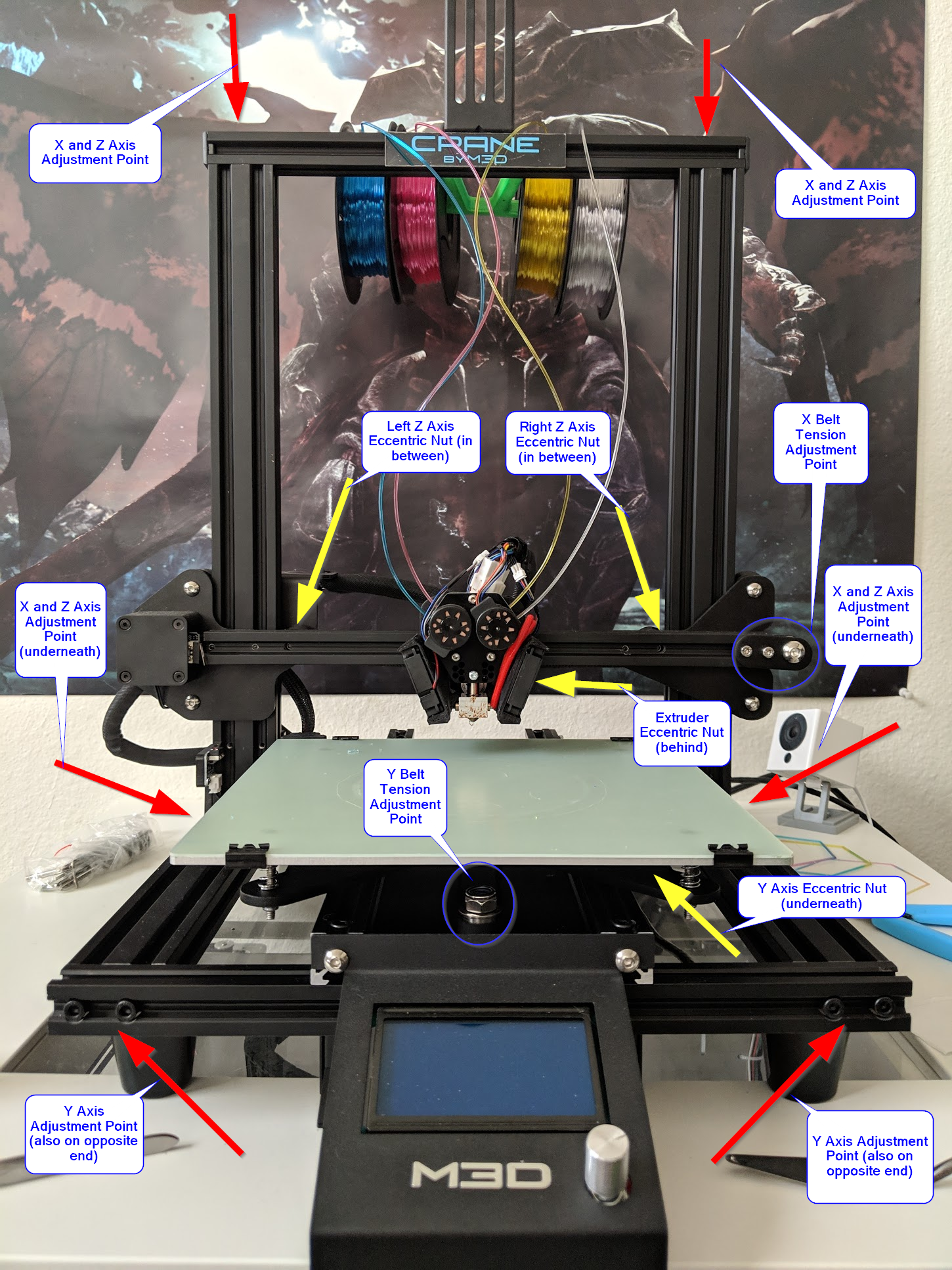
Each type of adjustment requires a different set of tools, so review the list below before getting started.
## Tools Required
For frame adjustments:
* 5mm hex key (allen wrench)
For eccentric nut adjustments:
* 10mm open end box wrench
* 8mm open end box wrench
* 4mm hex key
For belt tensioning adjustments:
* 6mm hex key (allen wrench)
* 12mm socket wrench
## How to Adjust
Before we begin, it is important to understand how each of these adjustment points function.
{% hint style="info" %}
The following frame adjustments were already performed at the factory and are not necessary for most users. You should only need to adjust the frame if you have previously taken the printer apart, or ave adjusted all eccentric nuts and are still experiencing binding at certain points on your axis.
{% endhint %}
**Frame Adjustment**
To adjust the frame adjustment points, you simply loosen the hex nut bolts in the frame (2 at each point) with a 5mm hex key and twist the metal frame extrusions slightly. There won't be much movement for most of the adjustment points, and it may feel like it's not moving at all, but it is important to ensure these contact points are equal and square, otherwise your axis may bind or you may have erratic print behavior at the extreme ends of your print volume.
**Eccentric Nut Adjustment**
Moving on to the eccentric nuts - This will be the most common type of tuning you perform on your printer. To begin adjustment of an eccentric nut, you take the 4mm hex key and place it in the hex head of the bolt running through the wheel and the eccentric nut. On the other end, you will place the 8mm open end box wrench and loosen the bolt slightly. It does not need to be very loose, and if it is too loose, that will impact your ability to adjust the eccentric nut effectively. Once the bolt is loosened slightly, you can then take the 10mm open end box wrench and spin he larger nut in between the wheel and the build plate. The nut is offset slightly so that as it spins it applies a different amount of pressure between the wheel and the plate. I recommend spinning the nut around completely at least once to get a feel for how the tension changes as it rotates around the bolt. Don't worry about "over tightening" the eccentric nut, as it doesn't actually tighten at all. It spins freely around the bolt with no threads running through the center. You can adjust the eccentric nut in either direction, so play around with it to get a feel for how it adjusts.
Once you've found the desired tension on the eccentric nut, you will need to tighten the bolt back down using the 4mm hex key and the 8mm open end box wrench using the same process you used to loosen it. You're not trying to tighten the bolt down completely, you're just trying to make it snug enough so that the eccentric nut cannot be moved easily and is held in place. It's important to note that when tightening the bolt, it will slightly tighten up the eccentric nut a little more than what you adjusted it to, so it may take a couple tries before you get the feeling down of how tight each eccentric nut and wheel should be.
## X Axis
Print Head Eccentric Nut

{% hint style="info" %}
When properly tuned, the print head should move easily side to side, but should not wobble front to back, nor should the x chassis wobble front to back on the chassis (See Z Axis tuning for adjustments of the X Chassis).
{% endhint %}
### Process
1. Begin by loosening the bolt holding the print head's eccentric nut.
2. Next, adjust the tightness of the eccentric nut by rotating it until the print head is held firmly in plac.
1. All 3 wheels should be in contact with the rail when properly adjusted.
2. When holding the print head steady, you should not be able to rotate any of the wheels on the print head chassis without also moving the print head.
3. Move the print head back and forth and attempt rocking it slightly
1. The print head should move left to right easily and the chassis should not rock front to back.
2. There may be a small amount of play in the connection of the print head to the bracket.
1. If this feels like it's too loose, you can remove the print head by loosening the eccentric nut's bolt until the wheel is loose enough to pop the print head chassis off. There are two screws on the back side of the chassis that you can use to tighten the print head to the print head chassis.
### Tuning Results
{% embed url="" %}
## Y Axis
Build Plate Eccentric Nut
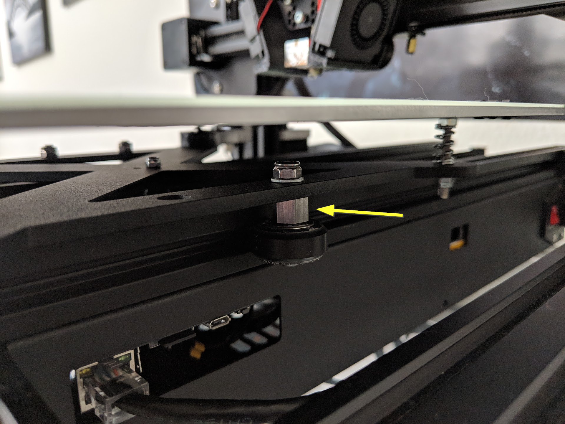
When properly tuned, the build plate should move front to back easily and smoothly, but should not rock or tilt. Having a tight and properly aligned build plate is important for ensuring a level, consistent bed. In addition to the eccentric nut on the build plate, the Y axis can also be adjusted by 4 frame mounting points, but this has been adjusted at the factory and is not necessary for most users. Only the eccentric nut adjustments are covered below.
### Process
1. Slightly loosen the bolt holding the build plate eccentric nut, under the right hand side of the build plate.
2. Adjust the eccentric nut for the Y axis until it the platform feels snug and sturdy, and the wheel cannot move without also moving the build plate.
3. Ensure the plate can move easily all the way along the Y axis.
1. If there are any tight spots, you may need to loosen the frame bolts related to the Y axis and re-tighten them evenly.
4. Once the Y axis is moving freely, tighten down the bolt holding the eccentric nut and test the movement once more.
### Tuning Results
{% embed url="" %}
## Z Axis
Z Chassis Left Eccentric Nut
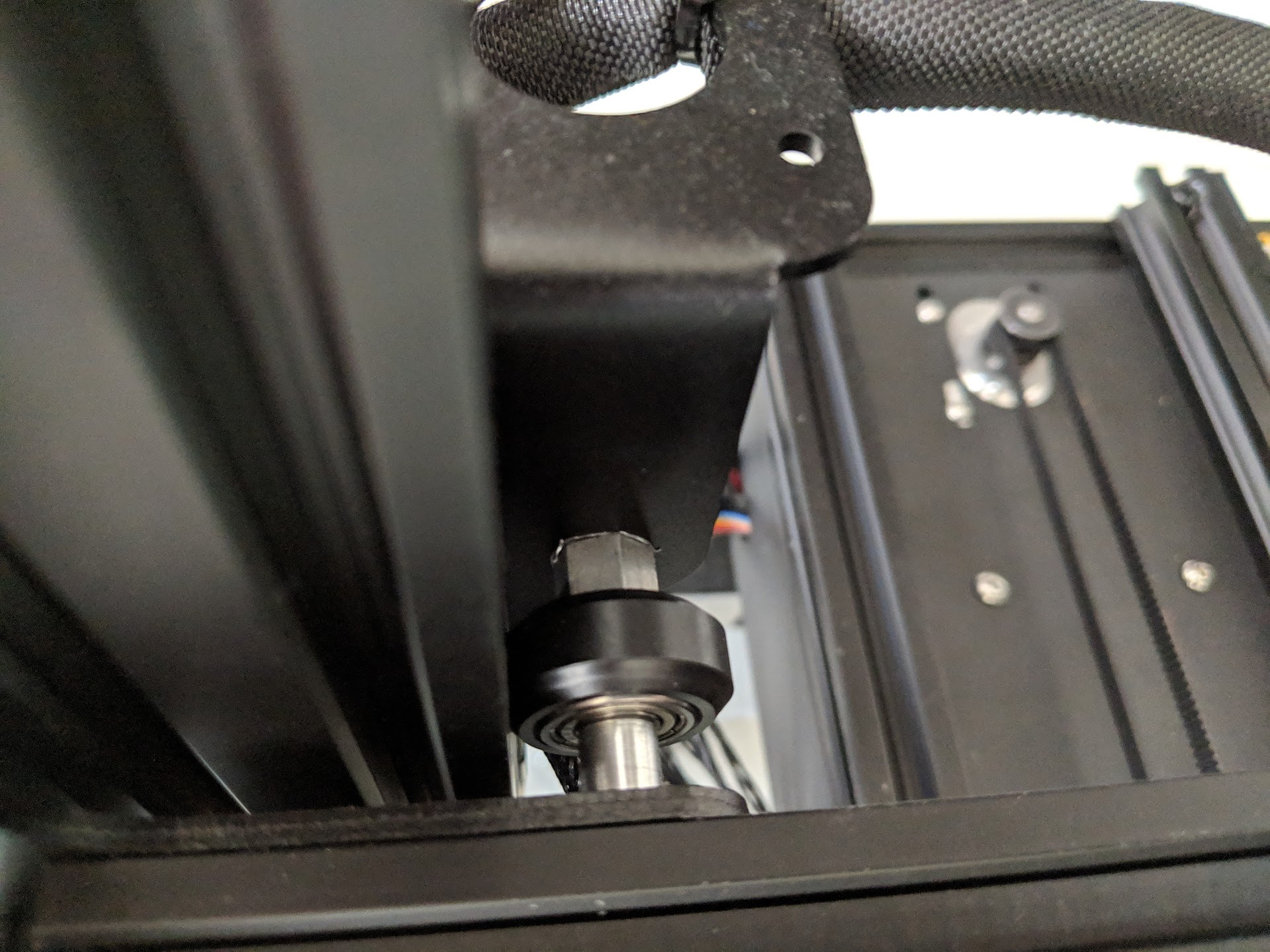
Z Chassis Right Eccentric Nut
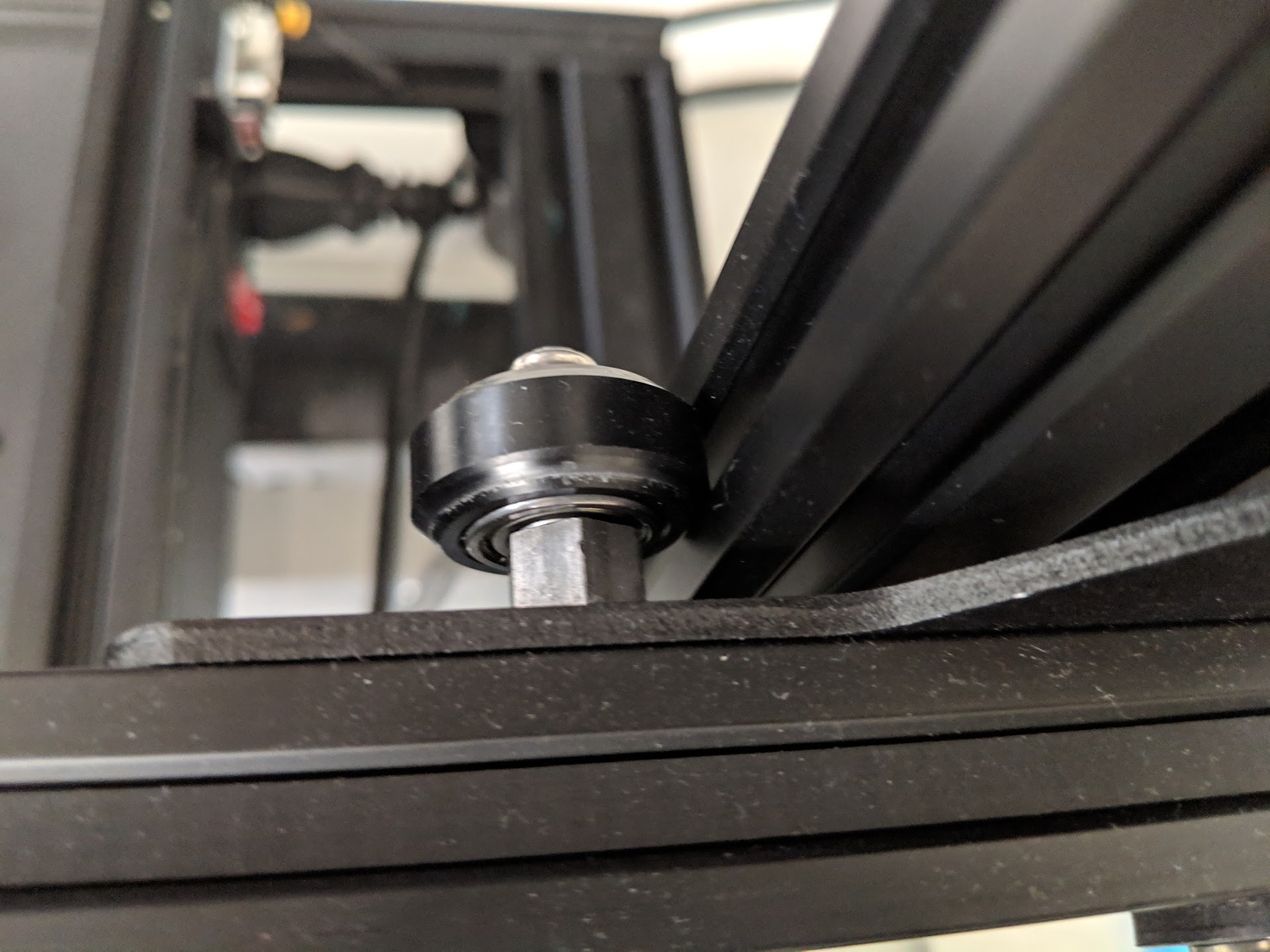
When properly tuned, the Z axis (X Chassis) should be able to move up and down with one hand and should not rock back and forth any. It should be evenly spaced to the top frame on the left and right side as well. Machine oil, or similar lubricants, can be used on the lead screw to aide in ease of movement. Lubrication of the lead screw plays a substantial part in the ease of movement of the Z axis and should generally be one of the first places you check if you are experiencing binding or rough spots in your Z movement. Under manual force, the movement should be consistent and smooth from top to bottom of the Z axis range.
There are 2 primary points of adjustment (eccentric nuts) and 4 secondary points of adjustment (frame attachment points). Only the eccentric nut adjustments are covered below.
### Process
1. Move the X Chassis all the way to the top or bottom of the axis (I recommend bottom).
2. Start by loosening the right side eccentric nut to the point that the wheel is still touching the frame, but can spin freely by hand without moving the chassis.
3. Afterwards, loosen the left side eccentric nut to the same point.
4. Test the movement of the X Chassis up and down.
1. It may be slightly difficult to move at this point due to some minor torquing of the chassis on the lead screw.
5. Adjust the left side eccentric nut so that it tightens up agains the railing a small amount.
1. At this point, the left eccentric nut wheel should be snug against the frame and the right side should still be slightly loose.
6. Go ahead and tighten up the right side eccentric nut until all three wheels are touching the frame and the wheel can no longer spin freely.
1. Each side (left and right) should feel tight, but not to the point of inhibiting movement.
7. Now, you can test moving the X Chassis up and down and feel how it moves.
1. There should be no wobble in the front to back direction, and the X Chassis should be capable of moving up and down with minor effort.
2. You can apply a small amount of machine oil to the 4 channels of the lead screw to aide in movement of the X Chassis. Move the chassis up and down slowly to help spread the oil along the lead screw
8. Tighten back down the bolts on the left and right side eccentric nut bolts and test movement again.
1. If the axis movement is too stiff after tightening the bolts, ensure you have not over-tightened them, then follow the above steps to loosen the eccentric nuts slightly in order to provide a little more movement freedom, re-tighten the bolts again, and check once more.
### Tuning Results
{% embed url="" %}
# Temperature Calibration
Proper temperature calibration is vital to allow for good print quality. The hot-end(s) and the bed are controlled by temperature feedback loops which are supposed to maintain a steady temperature. The type of feedback loop is a first order plus dead time ([FOPDT](https://controlguru.com/process-data-dynamic-modeling-and-a-recipe-for-profitable-control/)) loop. This loop has three different control variables: 1. Gain: Kp: Allows for manipulation of the strength of the heater response. 2. Time Constant: Tp: Control of the speed of the response of the heater. 3. Dead time: The delay before the system will begin a response.
This control loop and its variables are applied to the different heaters on the Crane. With the command `M303` and `M307` the temperature control loop can be tuned and changed. The default control variables supplied by M3D in the configuration files should allow you to print at a stable temperature. However, significant changes to the printing environment, such as room temperature, air-flow or humidity can impact your control loop effectiveness and stability. An improper control loop can cause problems listed below.
* **Overshoot**: A response to a new set-point will send the temperature of the heater significantly beyond the set-point. An overshoot of about 15°C is reasonable. A greater overshoot can cause your filament to char or present a fire hazard.
* **Oscillation**: An unstable control loop can result in a temperature oscillation. An oscillation of more than 5 °C degrees can impact printing quality.
* **Steady-state Error**: The stable temperature output of the control loop does not reflect the temperature set-point.
* **Long Response Timer**: The heater will take a long time to achieve the desired set-point. While not dangerous, this can be an annoying and unnecessary delay.
## Auto-tuning
RepRap firmware has a built in auto-tune heater function. This allows you to tune the control loop of a heater on the Crane. Follow the section below!
**WARNING: The auto-tune function can rapidly heat your hot-end(s) to a high temperature. DO NOT leave your printer unattended while running** `M303`
**Overview**
The command `M303` will heat-up your hot-end to a set-point temperature and record data as it does so. Therefore, while your hot-end is undergoing it is important to replicate the conditions that your 3D printer prints in. For example, turning on your nozzle fans. First, the tuning process will heat the hot-end to your set temperature. It will likely overshoot the set-point. The nozzle will then cool-down to room temperature. If you instructed the control board to perform multiple cycles, it will repeat this process multiple times. Once complete, the firmware will return suggested control variable values.
`M303` Parameters:
* `Hnnn`: Heater number (by default: 0 is bed, 1 & 2 hot-ends)
* `Pnnn`: PWM percentage from 0 to 1.
* `Snnn`: Set-point temperature in °C
`M307` Parameters:
* `Hnnn`: Heater number (by default: 0 is bed, 1 & 2 hot-ends)
* `Annn`: Gain constant
* `Cnnn`: Time constant
* `Dnnn`: Dead time
* `Fnnn`: PWM frequency
* `Bn`: Bang-bang control enable (1)
* `Snnn`: Maximum PWM
* `Vnnn`: Vin at the time of calibration. Allows for compensation of power supply voltage variation.
* Unload the filament from your hot-end. Once you are more familiar with the `M303` command, this step is not necessary. We recommend removing filament as it can burn and char inside your hot-end if the tuning process reaches a high temperature.
* Wait for the heater to reach room temperature. **This is important to achieve a good result!**
* Send the `M303` command. Change the `H` parameter to reflect the heater number. The PWM percentage can be changed with `P` if the heater is heating up too fast, and the firmware is unable to present control variables. The `S` parameter should be set to a typical printing temperature, such as 230°C. An example would be `M303 H1 P0.5 S230` in order to run auto-tune on hot-end 1, with 50% PWM and to 230°C.
* Wait for auto-tune to complete. Do not leave the printer unattended.
* The firmware should print out the calculated control variables. Sending `M303` should also display the control variables.
* Use the `M307` command in order to set new control variables. Use the parameter list above to determine the proper syntax.
* Remember to replace the `M307` command in the configuration file *config.g* with the command you just entered in order for your changes to take effect upon a system restart.
## Legacy PID Control
RepRap firmware also allows for control of the heaters with basic PID with three different constants: Kp, Ki, Kd. Use the command `M301` in order to send enable and send these control variables. These control variables also can be found by running the `M303` auto-tune as listed above. The command `M301` will enable the legacy PID control loop.
`M301` Parameters:
* `Hnnn`: Heater number
* `Pnnn`: Proportional constant (Kp)
* `Innn`: Integral constant (Ki)
* `Dnnn`: Derivative constant (Kd)
## Manually Tuning
Manually tuning your control variables can be done. Read more about the control variables explained in this guide online and their effects on a control loop before changing your control variables. Manually tuning your control variables is often a great option to reduce or obstruct observed errors as the ones listed above. Tuning your control loop from scratch is not recommended! Be careful when changing your control variables as it could easily produce unintended consequences
# Adjusting Homing Macros
Whenever you press the homing buttons located in the **Machine Control** tab of Duet Web Interface, execute a `G28` command, or a G-code file is set to home prior to printing, the respective homing macro is executed. Below you will find a brief explanation of each of the relevant homing macros.
## Homing Macros
The **sys/** folder, located in the root directory of the micro SD card contains the following files:
* **homeall.g**: This file contains G-code to home all three axes of the printer. This file is executed whenever the command `G28` is entered or whenever the **Home All** button on the Duet Web Interface is pressed.
* **homex.g**: This file contains G-code to home the X axis of the M3D Crane Series printer. This file is executed whenever the **Home X** button is pressed or when the `G28 X` command is sent.
* homey.g: This file contains G-code to home the Y axis of the M3D Crane Series printer. This file is executed whenever the **Home Y** button is pressed or when the `G28 Y` command is sent.
* **homez.g**: This file contains G-code to home the Z-axis of this printer. It is called whenever you press the **Home Z** button on the Duet Web Interface or `G28 Z` is sent.
# Filament Extrusion Rate
The extrusion system on the Crane is designed to print at specific speeds at certain temperatures. Printing at the proper filament extrusion rate is essential to provide a good print. The Crane is designed to extrude at a rate of 5.7 mm^3/s. This number can change significantly depending on your printer and slicer settings and material.
## Calculating Filament Flow Rate
Calculating the flow rate of your extruder is typically very easy. The equations you can use to calculate filament flow rate depends on your print settings and whether you are printing or not. Follow the *Extruding in Air* section to calculate the flow rate while extruding filament in the air and the *Printing Flow Rate* section in order to find the filament flow rate while printing.
### Extruding in Air
When the extruder is printing filament into air, we can assume that the printer is creating a steady stream of filament at a slightly larger diameter than the diameter of the nozzle. If the extruder is not skipping, you can use the feedrate of the extruder move and the cross-section of the filament to calculate the flow rate. Because, all the filament that is being pushed by the extruder is pushed through the nozzle. Follow the equation below:
*Flow Rate (mm^3/s) = Feedrate (mm/s)* (Filament Cross-section) (mm^2)\*
*Filament Cross-section = pi* ((Filament Diameter) / 2)^2 \_\_Filament Cross-section for 1.75mm filament: 2.405 mm^2\*
**For Example:** You send the command `G1 E100 F200`, where you extrude 100mm of filament at 200 mm/min. You are using 1.75 mm filament.
*Flow Rate = 8 mm/s = pi* (1.75 / 2)^2 *(200 / 60) = 2.405* 3.333\*
Remember that the `G1` move command feedrate parameter, `F`, uses mm per minute. So divide the feedrate by 60 to obtain the feedrate in mm per second.
### Printing Flow Rate
When printing, the flow rate depends on your layer height, nozzle diameter and print speed.
*Flow Rate (mm^3/s) = (Extrusion Width)(mm)* (Layer Height)(mm) *Print Speed (mm/s)* *Extrusion Width is \~120% of nozzle diameter*
**For Example:** You have a 0.5 mm nozzle mounted and you are printing at 0.25mm layer height at a print speed of 30 mm/s.
*Extrusion Width = 0.6 mm = 1.2* 0.5 *Flow Rate = 4.5 mm^3/s = 0.6* 0.25 \* 30
## Crane Flow Rate
The Crane is designed to extrude filament at 5.7 mm^3/s. If you find your extruder skipping or notice print quality problems, do a filament flow calculation to determine the extrusion rate you are printing at. The extrusion rate of the Crane can be increased significantly depending on material, printing temperature and other factors. Feel free to experiment and push the printer to its limits! But remember to calculate the filament flow rate to determine whether your goal is realistic.
# ABS-R Success Guide
Follow this step by step guide for successful printing with ABS-R.
## Material Table
| | First Layer | Printing |
| ------------------- | ----------- | -------- |
| Bed Temperature | 70°C | 60°C |
| Nozzle Temperature | 220°C | 235°C |
| Retraction Distance | - | - |
| Retraction Speed | - | - |
## Preparation
Follow the [Preparing a Print](https://m3d.gitbook.io/promega-docs/getting-started/preparing-a-print) guide for more help on slicing a print. Incorporate the material settings above into printing and bed temperature.
## Guide
1. Heat the bed up to ABS-R first layer temperature
2. Once the bed is hot, probe the bed with `G30` and then level the bed with `G29 S0`. Follow the [Bed Leveling & Probing](https://m3d.gitbook.io/promega-docs/repair-guides/repairing-broken-belt-clamps#leveling-the-bed) guide if you need help.
3. Heat up the nozzle to printing temperature and load filament. Follow the [Loading and Unloading Filament](https://m3d.gitbook.io/promega-docs/getting-started/loading-and-unloading-filament#loading-filament) guide. It is best to extruder about 10 mm of filament to make sure filament is flowing through correctly. Remember to clear the extruded filament with tweezers before starting the print.
4. Upload the print to the board. For more help follow the [Running a Print](https://m3d.gitbook.io/promega-docs/getting-started/running-a-print) guide.
## Quality Troubleshooting
Read the section below to improve the quality of your ABS-R print. The titles of the section below indicate the problems that you might see when printing ABS-R and how to solve them.
**Blobbing**
**Stringing**
**Under-extrusion**
# In-Depth Z-System Sequencing and Alignment
## Z-System Sequencing and Alignment:
The following video goes over how to insure your M3D Crane Series printer's Z-System is properly Sequenced and Aligned:
{% embed url="" %}
# About Community Submissions
## Community Support through Submissions:
{% hint style="info" %}
We welcome and encourage community submissions! If you are interested in contributing to our support community by submitting your own documentation, configurations, best practices, or settings, please submit your contribution through GitHub by first creating a GitHub account [here](https://github.com/).
{% endhint %}
## Using GitHub to submit your contribution:
Once you have made a GitHub account, navigate to the [PrintM3D ](https://github.com/PrintM3D)GitHub home page and select the repository that fits your contribution.
{% hint style="info" %}
If you are not familiar with GitHub reading through this short [tutorial ](https://guides.github.com/activities/hello-world/#branch)is helpful.
{% endhint %}
When you have reached the **correct repository** for your contribution, you will need to **create a branch** in order to make your edits, add your contribution, or make any other changes that will help support the PrintM3D Community.
Once you are happy with your changes, you are free to save them by clicking the **commit change**s button.
After your changes have been made, and saved within the new branch you will need to create a **Pull Request**. The Pull Request will alert our team that there are new submissions up for review within the PrintM3D repositories. If you would like your submissions to be reviewed by a specific M3D team member, or contributing member of the PrintM3D community you should use the [@mention system](https://help.github.com/articles/about-writing-and-formatting-on-github/#text-formatting-toolbar) when filling out your Pull Request.
# User Submitted Guides
## User Created Video Guides:
The following Video Guides were created by the user [**Tylerun**](https://www.youtube.com/channel/UCGeec2CuOivtNfsut2HUH1Q/featured)
## Firmware Updates:
{% embed url="" %}
## Duet Web Control Interface:
{% embed url="" %}
## Voxelizer 2 Setup and First Print:
{% embed url="" %}
## Voxelizer 2 Basic Color Switching:
{% embed url="" %}
We look forward to adding more Video Guides as well as other user submitted content! If you've created some user content and would like to submit it please refer to the section [**About Community Submissions** ](https://crane.printm3d.com/community-submissions-attributions/community-submissions)in order to have your content reviewed for publication.
# Attributions
The following is a list of all the models used by the M3D Crane Series teams along with their attributions. Links are provided should you choose to re-create these models.
| Model Name | Creator Name | Link to the Model |
| --------------------------------------------- | -------------------------- | -------------------------------------------------------- |
| 3 Color Vase | Thingiverse user jjpowelly | \ | | |
|
| | |
| Impossible to Manufacture | Thingiverse user Mathgrrl | |
| Zebra Vase | Thingiverse user Nextgen3D | |
| Seafarer Game Tile (ore) | Thingiverse user Dankanzla | \ | | |
|
| | |
| Bathtub Benchy | Thingiverse user Sipis | \ | | |
|
| | |
| Origami Crane | Thingiverse user Mirice | |
# Changelog
## October 30, 2018
+Added LCD menus for all Crane Series printers. LCD menus are specific to each Crane type, Dual, Quad, and Bowden.
+Added a config setting to enable the user to change the direction of their LCD encoder. See general.g
+Added Pause and Resume functionality to each of the Crane Series models, Dual, Quad, and Bowden.
+Multiple actions have been added to the encoder button (knob). For example when starting a print the LCD will display a “Print Started” screen with an option to go back when pressed again.
+Added “Test Prints” option to the idle screen of the LCD menu.
+Added a “Test Print” menu, providing 3 test prints to select from. Test Print “draft” model, Bed level test, and Hex test.
\
\- LCD Menu Issue: Change movement axes and extrusion menus on LCD so that + and - are reversed.
-LCD Menu Issue: Change filament numbering to reflect current drive sticker layout.
-SD/Config Issue: Add community contributions to all models included on the SD card.
## October 26, 2018
## Initial Release:
+This is initial release (version one) of the Change Log for the **M3D Crane Series** of printers. The purpose of this document is to track known issues, feature additions, bug reports and resolutions.
+Added state based instructions to the LCD Menu. While printing/paused, the "Tune" button will now appear on the main display. In an idle state the "Prepare" button will appear in its stead.